

Your task
Increasing processing power and storage speed in modern data centers drive the evolution of PCI Express (PCIe) data rates. At link speeds of 32 GT/s (PCIe 5.0) and 64 GT/s (PCIe 6.0), insertion loss in PCB signal traces is too high. Thus, high-speed PCIe signals are increasingly being transmitted via cable assemblies that bypass the PCB. This significantly reduces insertion loss and allows longer distances between the PCIe root complex and the PCIe endpoints without exceeding the defined channel budgets for insertion loss, return loss, crosstalk and skew.
With the CopprLink Internal and CopprLink External Cable and Connector specifications for PCIe 5.0 and 6.0, PCI-SIG has defined standard cable and connector configurations for internal cables (inside a chassis) and external cables (chassis-to-chassis) along with the corresponding test items and limits for compliance testing. Custom cable assemblies typically also use these test items with corresponding adaptations of the limits for pass/fail analysis. Testing PCIe cables presents many challenges and requires powerful test automation for efficient and reliable testing.
The PCIe link between the root complex and the endpoint device consists of multiple lanes, each of them representing one differential signal path for transmission and one for reception. A lane width of x4, x8 or x16 consists of 8, 16 or 32 differential signal paths requiring measurement with 32, 64 or 128 ports, respectively. According to PCIe 5.0/6.0 CopprLink Internal Cable and CopprLink External Cable specifications, test items include insertion loss (IL), return loss (RL), near-end crosstalk (NEXT) with PowerSum NEXT (PSNEXT), far-end crosstalk (FEXT) with PowerSum FEXT (PSFEXT), effective intra-pair skew and lane-to-lane skew. The specifications also define integrated return loss (iRL) and component‑contributed integrated crosstalk noise (ccICN NEXT and ccICN FEXT) as waiver criteria for cases where the corresponding limit lines are violated.
For a complete test of x4, x8 or x16 cables, 64, 256 or 1024 4-port measurements, respectively, are required. To avoid measurement errors during crosstalk tests, the unused ports need to be terminated.
For cables assemblies and connectors with PCIe transmission on their sideband signals, the number of required test ports and measurements can be even higher. Test automation is key because manual measurements are extremely time consuming and prone to connection errors.
Application
The measurement of a PCIe 5.0/6.0 cable typically includes the following steps:
- Accurate test fixture modeling and deembedding:
The specification defines the reference plane close to the cable connector on the test fixture. Each lead-in needs to be accurately characterized and deembedded, i.e. mathematically removed from the test results. Impedance corrected deembedding is required to accurately model each lead-in on the test fixture with its specific impedance profile and ensure accurate measurement results. - Calibration of the multiport setup:
PCIe x4, x8 and x16 cable configurations require measurement setups with 32, 64 and 128 ports. Including sideband signals further increases the required port count. Calibrating this setup can be quite cumbersome and error-prone. - Measurement of all THRU and crosstalk paths:
PCIe x4, x8 and x16 cable configurations require a total of 64, 256 and 1024 4-port measurements; including sideband signals increases the count further. Test automation is essential to prevent connection errors and perform these measurements efficiently. - Postprocessing and report generation:
For accurate pass/fail analysis in the test report, the iRLmand ccICN metrics also have to be calculated.
| PCIe lane configurations, testing and calibration requirements | |||
|---|---|---|---|
| Lane width | PCIe x4 | PCIe x8 | PCIe x16 |
| Number of lanes | 4 | 8 | 16 |
| Differential signal paths (TX and RX) | 8 | 16 | 32 |
| Number of ports for full testing (all lanes and all crosstalk combinations) | 32 | 64 | 128 |
| Number of 4-port measurements for full testing (all lanes and all crosstalk combinations) |
8 × THRU 4 × 4 = 16 × NEXT_L 4 × 4 = 16 × NEXT_R 3 × 4 = 12 × FEXT_L 3 × 4 = 12 × FEXT_R total: 64 × 4-port measurements |
16 × THRU 8 × 8 = 64 × NEXT_L 8 × 8 = 64 × NEXT_R 7 × 8 = 56 × FEXT_L 7 × 8 = 56 × FEXT_R total: 256 × 4-port measurements |
32 × THRU 16 × 16 = 256 × NEXT_L 16 × 16 = 256 × NEXT_R 15 × 16 = 240 × FEXT_L 15 × 16 = 240 × FEXT_R total: 1024 × 4-port measurements |
| Standard calibration (three connections per 4-port) | 64 × 3 = 192 | 256 × 3 = 768 | 1024 × 3 = 3072 |
| Optimized calibration | 31 connections | 63 connections | 127 connections |

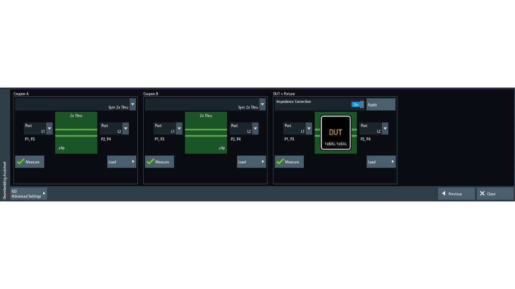
Rohde & Schwarz deembedding assistant: example with R&S®ZNx-K220 in-situ deembedding option
Rohde & Schwarz deembedding assistant: example with R&S®ZNx-K220 in-situ deembedding option
Open Lightbox
Rohde & Schwarz solution
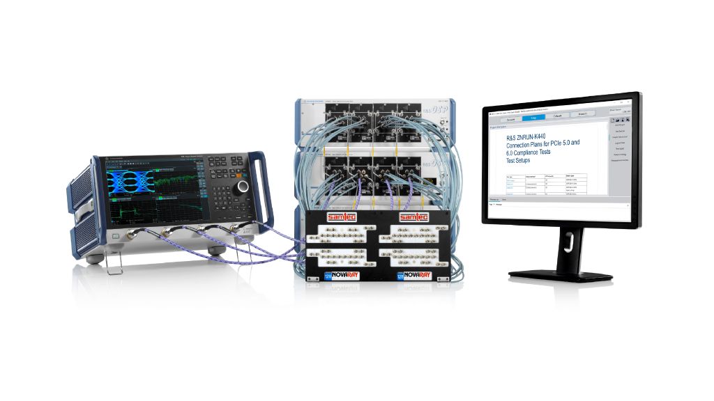
Rohde & Schwarz provides a fully automated compliance test solution based on Rohde & Schwarz vector network analyzers, the R&S®OSP320 open switch and control units and the R&S®ZNrun automation software. The solution enables compliance tests according to the CopprLink Internal and CopprLink External Cable and Connector specifications for PCIe 5.0 and 6.0 and can be easily be adapted to meet compliance testing requirements for custom PCIe 5.0 and 6.0 cables. Extending the frequency range beyond the current requirements of PCIe 5.0/6.0, means that this solution also meets the requirements of the upcoming PCIe 7.0 cable and connector test specifications.


VNA with deembedding assistant for accurate test fixture characterization and deembedding
The test fixture typically includes one 2x-THRU reference structure and numerous lead-ins. Because all of these structures have different orientations to the fiber weave structure of the test fixture, they each have different impedance profiles. Accurate impedance correction is required to precisely model each lead-in with its own impedance profile and ensure correct deembedding with no phantom limbs.
Accurate impedance correction with the Rohde & Schwarz deembedding assistant (right image), showing results of the total DUT and fixture structure and the deembedded DUT: example with R&S®ZNx-K220. Comparison of time domain reflectometry (TDR) results shows the difference in impedance profiles between the 2x-THRU reference structure, the A02_A03 total structure and the A14_A15 total structure. The calculated lead-in fixture model for A14_A15 perfectly conforms to the impedance profile of the A14_A15 total structure. The lead-in is completely removed, the impedance profile of the deembedded DUT shows no phantom limbs.


With the R&S®ZNx-K210 (EZD), R&S®ZNx-K220 (ISD) and R&S®ZNx-K230 (SFD) deembeding options, Rohde & Schwarz vector network analyzers offer powerful workflow implementation for impedance corrected test fixture characterization and deembedding with industry-leading accuracy. The deembedding assistant guides users through the steps of defining the DUT topology, measuring the deembedding reference structures (typically 2x-THRU coupons) and the total structure (DUT and fixtures), calculating the fixture models and deembedding them from the measurement result. Thanks to integration into the instrument, measurement results can immediately be viewed and analyzed.
PCIe 5.0 and 6.0 use a frequency range of 10 MHz to 24 GHz with a step size of 10 MHz for cable and connector testing. However, a frequency range of 40 GHz typically yields better time-domain resolution during test fixture characterization and deembedding and offers better accuracy of the derived model; it is therefore recommended for the test. The table below contains a list of the recommended VNA models and their configurations.
| Recommended VNA models and their configurations | |
|---|---|
| Designation | Type |
| Frequency range up to 43.5 GHz | |
| 4-port VNA, 9 kHz to 32 GHz, 2.92 mm | R&S®ZNB3032 |
| Frequency upgrade R&S®ZNB3032 to 43.5 GHz, 4-port, 2.92 mm | R&S®ZNB3-B444 |
| Time domain analysis | R&S®ZNB3-K2 |
|
EaZy deembedding (EZD) In-situ deembedding (ISD) Smart fixture deembedding (SFD) |
R&S®ZNB3-K210 or R&S®ZNB3-K220 or R&S®ZNB3-K230 |
| 2-port calibration unit, 2.92 mm, 9 kHz to 40 GHz (characterized up 43.5 GHz) | R&S®ZN-Z54 |
| Frequency range up to 54 GHz | |
| 4-port VNA, 9 kHz to 43.5 GHz, 1.85 mm | R&S®ZNB3044 |
| Frequency upgrade R&S®ZNB3044 to 54 GHz, 4-port, 1.85 mm | R&S®ZNB3-B544 |
| Time domain analysis | R&S®ZNB3-K2 |
|
EaZy deembedding (EZD) In-situ deembedding (ISD) Smart fixture deembedding (SFD) |
R&S®ZNB3-K210 or R&S®ZNB3-K220 or R&S®ZNB3-K230 |
| 2-port calibration unit, 1.85 mm, 10 MHz to 67 GHz | R&S®ZN-Z156 |
| Frequency range up to 67 GHz | |
| 4-port VNA, 10 MHz to 67 GHz, 1.85 mm | R&S®ZNA67 |
| Time domain analysis | R&S®ZNA-K2 |
|
EaZy deembedding (EZD) In-situ deembedding (ISD) Smart fixture deembedding (SFD) |
R&S®ZNA-K210 or R&S®ZNA-K220 or R&S®ZNA-K230 |
| 2-port calibration unit, 1.85 mm, 10 MHz to 67 GHz | R&S®ZN-Z156 |
Predefined matrix configurations with semi-rigid cable sets
Predefined switch matrix configurations are available with 24 ports, 44 ports and 64 ports for 40 GHz (2.92 mm) and 67 GHz (1.85 mm). The solution is customizable, supporting various switch matrix configurations up to 144 ports. The switch matrices include modules with high-performance, terminated SP6T switches. They connect the vector network analyzer to the differential signal path under test and terminate all other paths to avoid measurement errors due to unwanted reflections during the crosstalk tests.
For best return loss and phase stability, semi rigid cables are recommended. The tables below provide an overview of typical, predefined matrix configurations for PCIe cable and connector tests and the semi rigid cable sets required.

| Recommended setup for 44 ports | ||
|---|---|---|
| Designation | Type | Quantity |
| Frequency range up to 40 GHz | ||
| Open switch and control platform | R&S®OSP320 | 2 |
| SP6T switching module, DC to 40 GHz, terminated, 2.92 mm | R&S®OSP-B122H | 8 |
| Semi rigid x4 cable set R&S®ZNB3032 to R&S®OSP, 40 GHz, 2.92 mm | R&S®ZV-ZB40 | 1 |
| Semi rigid x4 cable set R&S®OSP to R&S®OSP, 40 GHz, 2.92 mm | R&S®ZV-Z40X4 | 1 |
| Frequency range up to 67 GHz | ||
| Open switch and control platform | R&S®OSP320 | 2 |
| SP6T switching module, DC to 67 GHz, terminated, 1.85 mm | R&S®OSP-B122VL | 8 |
|
Semi rigid x4 cable set R&S®ZNB3044 to R&S®OSP, 67 GHz, 1.85 mm; Semi rigid x4 cable set R&S®ZNA67 to R&S®OSP, 67 GHz, 1.85 mm |
R&S®ZV-ZB67 or R&S®ZV-ZA67 |
1 |
| Semi rigid x4 cable set R&S®OSP to R&S®OSP, 67 GHz, 1.85 mm | R&S®ZV-Z67X4 | 1 |

| Recommended setup for 64 ports | ||
|---|---|---|
| Designation | Type | Quantity |
| Frequency range up to 40 GHz | ||
| Open switch and control platform | R&S®OSP320 | 3 |
| SP6T switching module, DC to 40 GHz, terminated, 2.92 mm | R&S®OSP-B122H | 12 |
| Semi rigid x8 cable set R&S®ZNB3032 to R&S®OSP, 40 GHz, 2.92 mm | R&S®ZV-ZB40X | 1 |
| Semi rigid x8 cable set R&S®OSP to R&S®OSP, 40 GHz, 2.92 mm | R&S®ZV-Z40X8 | 1 |
| Frequency range up to 67 GHz | ||
| Open switch and control platform | R&S®OSP320 | 3 |
| SP6T switching module, DC to 67 GHz, terminated, 1.85 mm | R&S®OSP-B122VL | 12 |
|
Semi rigid x8 cable set R&S®ZNB3044 to R&S®OSP, 67 GHz, 1.85 mm; Semi rigid x8 cable set R&S®ZNA67 to R&S®OSP, 67 GHz, 1.85 mm |
R&S®ZV-ZB67X or R&S®ZV-ZA67X |
1 |
| Semi rigid x8 cable set R&S®OSP to R&S®OSP, 67 GHz, 1.85 mm | R&S®ZV-Z67X8 | 1 |
Test automation
The R&S®ZNrun automation software with the R&S®ZNrun-K400 and R&S®ZNrun-K440 options enables easy, precise and time-saving compliance testing of cable assemblies and cable connectors according to the CopprLink Internal and CopprLink External Cable specification for PCIe 5.0 and 6.0. It automatically measures IL, RL, NEXT including PSNEXT, FEXT including PSFEXT, effective intra-pair skew and lane-to-lane skew of the various differential signal pairs. The software calculates the corresponding iRL, ccICN NEXT and ccICN FEXT metrics and generates a comprehensive test report with a pass/fail verdict.
The solution offers
- High flexibility to support different types of cable assembly and connector configurations. Besides standard test plans for PCIe x4, x8 and x16 with 4, 8 or 16 lanes, the user can easily generate test plans for cables and connectors with different lane counts. This is highly useful for cables and connectors with PCIe transmission on sideband signals. If the selected lane count is higher than the number of ports available in the vector network analyzer plus switch matrix configuration, users are guided through the required connection steps and prompted, whenever a new connection of the switch matrix to the test fixture and new port terminations on the test fixture are required.
- High flexibility in setting up the measurements based on the generated test plan. Instead of complete measurement of all lanes and with all test items, measurement can be restricted to specific lanes and specific test items. Limit lines can be adapted to meet the requirements of custom cable assemblies and connectors.
- An optimized calibration routine that significantly reduces the number of calibration connections. The routine is based on a star calibration and reduces the number of calibration connections in PCIe x4, x8 and x16 configurations as shown on page 3. PCIe cable assemblies and connectors that have high-speed transmission on sideband signals, the number of lanes, ports and calibration connections increase accordingly
- Fully automated measurement, calculation of the corresponding metrics and test report generation with a pass/fail verdict, which saves test time and prevents connection errors. The software always connects the vector network analyzer to the right differential signal pair and terminates all other ports.
- A comprehensive API to control the test automation remotely from other software.
Summary
The test solution offers automated cable assembly and connector compliance tests in line with the CopprLink Internal and External Cable and Connector specification for PCIe 5.0 and 6.0 and is upgradeable to the future requirements of PCIe 7.0. Automation provides fast and accuratecalibration and measurements as well as a full test report with a pass/fail verdict. It automatically switches the vector network analyzer to the differential signal path under test and terminates all other signal paths to avoid unwanted reflections during the crosstalk measurements.Thanks to its high level of flexibility, the solution can easily be adapted to custom cable configurations, test plans and limit lines. With its API interface, the software can also be integrated into an existing software environment. The solution addresses the needs of compliance testing and beyond, also covering R&D and regression as well as production testing.
| Recommended software configuration | |
|---|---|
| Designation | Type |
| License dongle, mandatory for R&S®ZNrun | R&S®ZNPC |
| R&S®ZNrun core software | R&S®ZNRUN-K1 |
| Signal integrity base option for cable and connector assembly test | R&S®ZNRUN-K400 |
| Compliance test software automation for PCIe 5.0 and 6.0 | R&S®ZNRUN-K440 |


Related products


