Analyzing common mode noise of EPS for flawless touchscreen operation
Modern, capacitive touchscreens as used, for example, in mobile phones are susceptible to common mode noise exhibited by external power supplies (EPS).

Modern, capacitive touchscreens as used, for example, in mobile phones are susceptible to common mode noise exhibited by external power supplies (EPS).
Modern, capacitive touchscreens as used, for example, in mobile phones are susceptible to common mode noise exhibited by external power supplies (EPS). Capacitive touchscreenswork by measuring the capacitance of a human fingertip to a ground reference. If the operating touch device is connected to an EPS, the common mode influence on the ground reference can significantly distort the measured capacity. This EPS is effectively in the voltage loop for the capacitance measurement. Measuring and characterizing the EPS in line with standards as described, for example, in the Guide on Implementation of Requirements of the Common EPS or IEC 62684 ensures flawless operation of handheld devices with capacitive touch displays.
For the test setup, the EPS is connected to the mains with 90 V to 264 V (L). The common mode noise between the n port and protective earth (PE) is measured (see Fig. 1). The trace is periodic to the line frequency, but clipped, with an estimated magnitude of 200 V (Vpp). The line signal dominates the pulses caused by the EPS, but it does not harm touchscreen operation. The issues are caused by the pulses. The zoom (Fig. 1) of the measured voltage V(n, PE) shows the common mode noise (CMN) caused by the switched mode power supply (SMPS) as a sequence of pulses overlaid by the line signal. It also shows significant noise due to insufficient resolution. The relative magnitude of the SMPS pulse is measured as the difference between the cursors (ΔV = –5.4 V). The task is to measure the worst-case pulse signal. But since there are a few hundred pulses per line period, the zoom window would need to be manually adjusted all the time to measure every pulse. Automated measurements are not available for this case. Two things are required to measure successfully and fast:


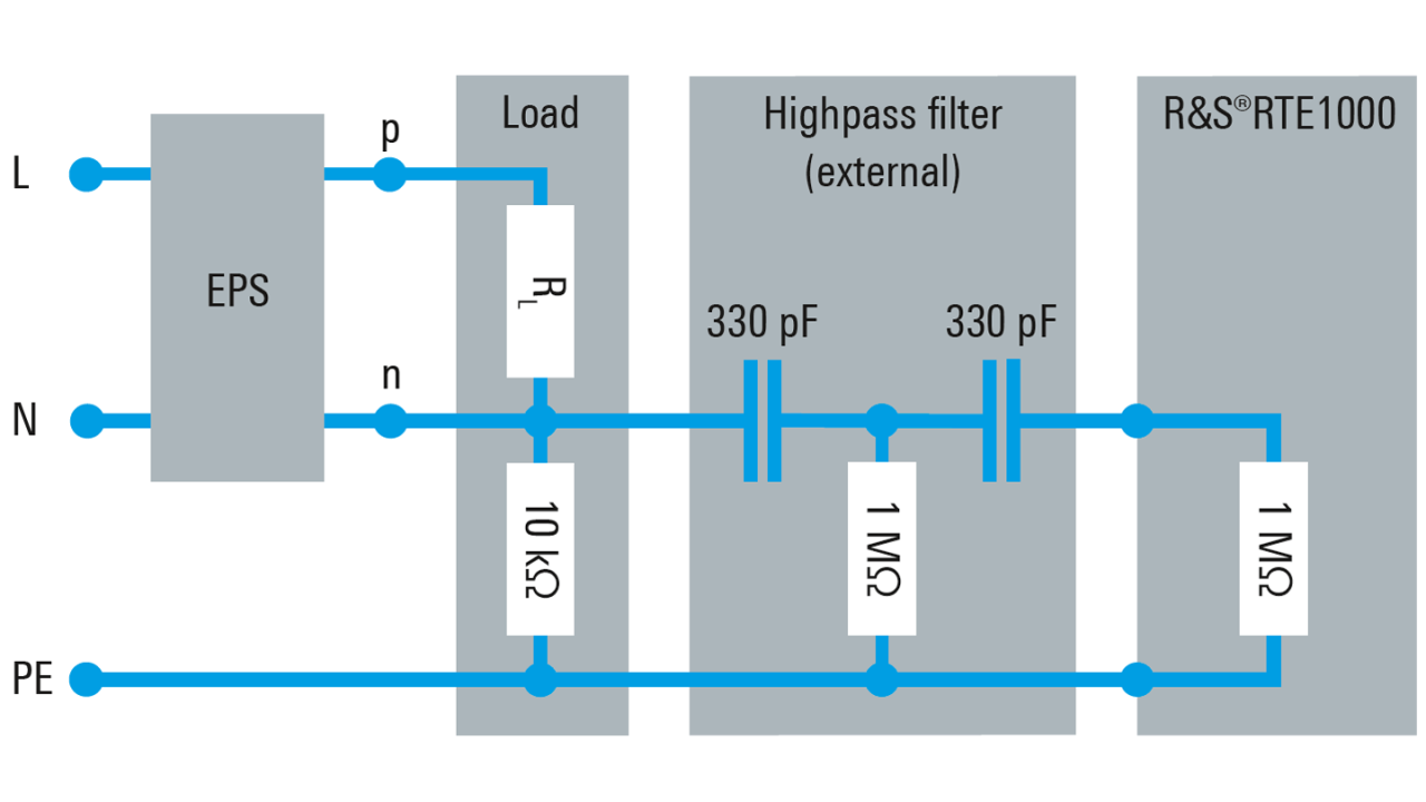
Fig. 2: Test setup to measure the common mode noise of an EPS
An R&S®RTE1000 or R&S®RTM3000 oscilloscope solves these requirements in combination with an external highpass filter (fC = 1 kHz; (330 pF/1 MΩ) || (330 pF/1 MΩ [oscilloscope’s input impedance])) and a load (RL and 10 kΩ) in line with the Guide on Implementation of Requirements of the Common EPS requirements (Fig. 2). The filter removes the line signal component (see Fig. 3 top trace). The resolution is improved by using an optimal vertical scale of 1.25 V/div to display the CMN signal. The line trigger ensures a stable trace display. To capture one line period in less than 20 Msample, downsampling is applied. This also allows the use of the high resolution (HiRes) mode and further improves the resolution.
The search functionality of the R&S®RTE1000 and R&S®RTM3000 oscilloscopes makes evaluation of the common mode noise straightforward. To find the worst case, the pulse width search is used with a width of 1.5 μs ±0.3 μs (from the cursor measurement in Fig. 1) and a level of 2 V (as defined in the Guide on Implementation of Requirements of the Common EPS). The oscilloscope returns all SMPS pulses that exceed the specified level. Fig. 3 shows the results in the CMN pulse list. The trace zoom is of the selected pulse in the list. Using the up/down arrow, the user can scroll through all violations and find the worst-case pulse.
Both negative and positive pulses in the list can be analyzed with a cursor or an automated measurement. In Fig. 3, automated, gated measurements analyze the selected pulse (low: –3.71 V; negative pulse duration: 1.66 μs) and are in line with the cursor measurement. Both measurement results are encircled in red (see Fig. 3 right side). Note that the vertical "low" measurement averages out the ringing of the pulse. The ringing is observed in the beginning, but with durations smaller than 250 ns it does not impact the measurement as requested by the Guide on Implementation of Requirements of the Common EPS.
The R&S®RTE1000 and R&S®RTM3000 oscilloscopes provide the right tools to quickly analyze the CMN of an EPS. With an external highpass filter and a standard-compliant load, the R&S®RTE1000 and R&S®RTM3000 can analyze a large set of SMPS pulses to check conformance. The example here shows a negative pulse. Positive pulses can be analyzed in the same manner.