Electronically steerable frontend for qualifying automotive radar
World’s first fully electronically steerable antenna array.
World’s first fully electronically steerable antenna array.
Your task
Autonomous driving (AD) and advanced driver assistance systems (ADAS) are a major driver of innovation in the automotive industry. Radar sensors are one of the key technologies for AD and ADAS and they need to be tested for different scenarios, such as pedestrians (an object crossing in front of the car), driving in the city (driving towards a stationary or slower vehicle) and inter-urban travel (similar to city travel where the centerline of the test vehicle is not in line with the center of the target).
Hardware-in-the-loop (HIL) and vehicle-in-the-loop (VIL) test scenarios with more complex target simulation capabilities are needed to reach ADAS levels 4 and 5. Demand is also increasing for benchtop radar simulation and functional tests to speed up the validation process (Fig. 1).


Fig. 1: ADAS levels and degree of automation: potential vehicle configurations
Today, OEMs and engineering service providers use simulated environments with software-in-the-loop systems to test sensors and control modules. Software simulations are valuable, but they cannot replicate the real-world and potentially imperfect sensor responses. Fully autonomous vehicles must deal with these irregularities. Road testing an entire integrated system in a prototype or road-legal vehicle is necessary since it allows OEMs to validate a final product before a market launch. Road testing is important to the development process but road tests alone are not enough: they are costly, time consuming and difficult to replicate.
Further testing is needed across the whole sensor development value chain and simple use cases such as testing single radar sensor components and testing complex scenarios with multiple sensors must be integrated. The goal is to test autonomous driving functions such as adaptive cruise control or emergency breaking systems under various lab conditions (see Fig. 2).
Realistic and repeatable radar sensor testing is challenging in the sensor value chain:
1) Reduction of sensor noise floor as well as suppression of close range targets and potential multipath reflections.
Rohde & Schwarz solution
Current target simulators use horn antennas as frontends, where each point targets radar sensors and emulates horizontal and vertical positions by mechanically moving the antenna. Mechanical automation slows overall test times. Each antenna movement changes the echo’s angle of arrival (AoA), leading to errors and loss of accuracy when rendering targets when the antennas are not recalculated or recalibrated.
To overcome current system limitations and address the growing importance of HIL and VIL, Rohde & Schwarz has developed the R&S®QAT100 advanced antenna array – the world’s first electronically steerable antenna array. The R&S®QAT100 simulates azimuth and elevation by activating small patch antennas. The switching time between the antennas is about 2 ms to simulate quickly moving azimuthal targets (e.g. cross traffic at an intersection or passing scenarios).
Overview of radar sensors


OTA radar stimulation in elevation and azimuth without physically moving antennas
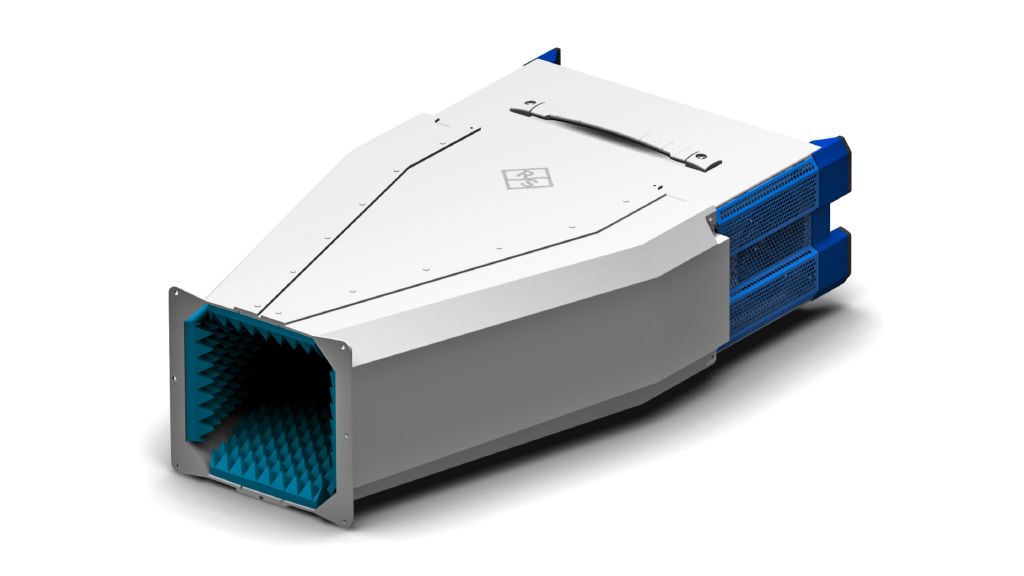
Clean RF: no reflections from FE
The PCB antennas have a much lower RCS than the standard gain horns used in other systems. The R&S®QAT-B50 shielding system ensures a shielded RF environment.
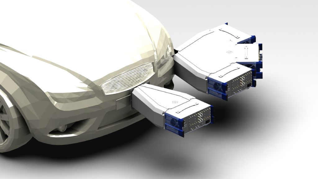
Scalable solution
Several frontends can be combined to simulate up to 360° of radar environment:
Immune to vibration: perfectly fitted for VIL testbed mounting
1) Field of view.
Use cases
The modular setup of the R&S®QAT100 can be used in various different applications for radar target simulations.
Component or functional testing
It starts with very simple use cases such as component testing for a single radar sensor. To test if a radar sensor correctly detects an echo, distinguishes between two targets at a given distance or a given angle and the angular resolution of your radar sensor.
Scenario testing
Secondary use cases include scenario testing, such as traffic scenarios with multiple cars, emergency breaking systems or adaptive cruise control. The goal is to simulate moving targets in azimuth, range, radial velocity and target size. Depending on the scenario, one or several sensors can be simulated.


The R&S®QAT100 has the versatility and capability to support the entire process along the radar sensor chain.
Starting with the R&S®QAT100 as a standalone device for radar sensor performance evaluation in the early stages with classical benchtop setups, to HIL and VIL applications (with target simulator as backend) at the radar sensor module level when adapting a sensor to OEM specifications(Fig. 6).


The R&S®QAT-B11 standard frontend has 96 transmit and 5 receive antennas, divided into 4 independent segments. The configuration meets SIMO sensor requirements. The R&S®QAT100 can be operated in line mode or in segment mode, depending on what is required. Segment mode divides each line into four segments, where each has an individual RF connector and can simulate up to four targets from different directions. The R&S®QAT-B11 can come with an additional TX/RX line (R&S®QAT-B2) to add another 96 transmit and 5 receive antennas to simulate up to 8 targets from different directions or two objects across the complete array.
The larger offset between RX and TX antennas means the R&S®QAT-B11 does not fully meet MIMO requirements since it can be jumped at different angles. The R&S®QAT-B21 single-line MIMO frontend has one line of receive and one line of transmit antennas. Every transmit antenna is paired with a receive antenna to meet MIMO requirements. 96 receive and 96 transmit antennas are now available to minimize phase errors and enable easy validation of MIMO radars with improved spatial echo resolution in three dimensions.
The individual antennas are 3.7 mm (0.146 in) apart, while the total unit width is 351 mm (13.818 in). The setup can be tailored to the sensor. The R&S®QAT100 is designed for typical ADAS radar transmission power.
The field of view (FOV) and achievable angular resolution for the R&S®QAT100 are based on the setup and are calculated as follows:

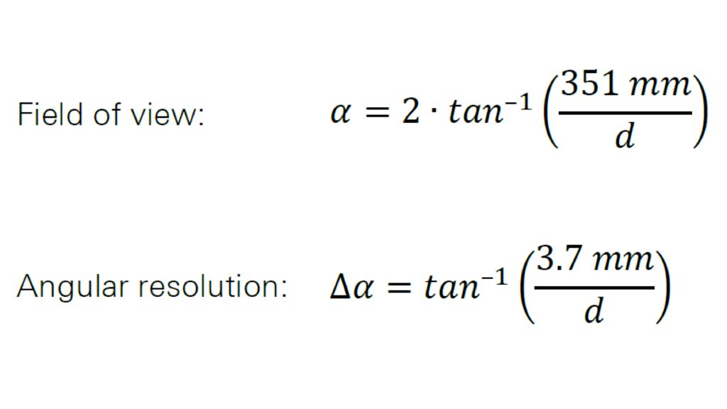


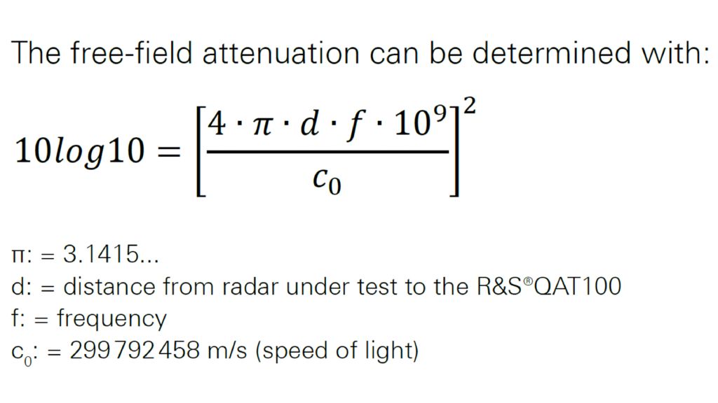
Depending on distance and frequency range, the following values apply:


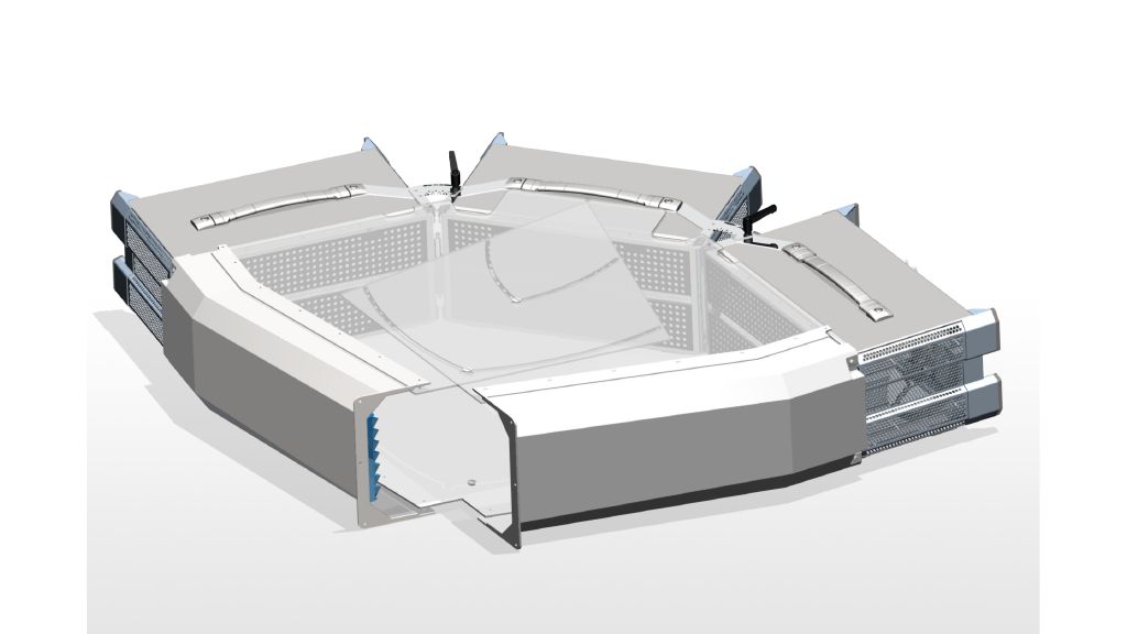
To minimize the influence of external interference, an additional shielding system provides a nearly interference-free RF environment perfectly suited to the R&S®QAT100. The shielding system can be used in aboratories on benchtops or in vehicle test stands. The shielding provides a multipath and reflection-free environment for the radar under test. When combined with the R&S®QAT100, small patch antennas with an absorber covered surface provide a clean RF frontend and suppress close-range targets as well as potential multipath reflections (see Fig. 10).
Fig. 10: Shielding and mounting set
The shielding system connects with the R&S®QAT100 and shields radars from external signals. It is available in different sizes depending on the number of connected R&S®QAT100 advanced antenna arrays (e.g. R&S®QAT-Z50 shielding system, R&S®QAT-Z53 shielding trio).


The number and types of connections to a radar echo generator depend on the complexity of the test setup. The setup complexity depends on the number of simulated radar objects, the number of R&S®QAT100 advanced antenna arrays or the number of receive antennas (receive antennas always receive, but can only forward a signal when connected to a backend).
Depending on the number of individually controlled antenna segments, a radar echo generator must have a certain number of inputs:


Fig. 11 - Variant 1 Connect the transmit signal to the “TX Σ” connector. All transmit antennas share the same signal now.

Fig. 11 - Variant 2: Connect the transmit signal from “TX A” to “TX D” connector. Each antenna segment can transmit a different signal now, enabling up to four targets per TX line. Connect the RX antennas to the “RX IF In” on the radar echo generator. If you want just a single receive signal from the radar echo generator, connect the “RX Select” to one “RX IF In”. To connect other external devices such as a spectrum analyzer, use the “RX Select” connector.
To synchronize reference frequencies, connect the frequency reference (input or output) to the radar echo generator.
When equipped with the R&S®QAT-B2 second line of 96 transmit antennas, the R&S®QAT100 has two lines with four independent segments each, enabling a single instrument to connect to eight individually controllable IF paths. This combines perfectly with the eight completely independent artificial objects simulated by a fully equipped R&S®AREG800A automotive radar echo generator. Each IF path can be freely steered within an R&S®QAT100 segment.
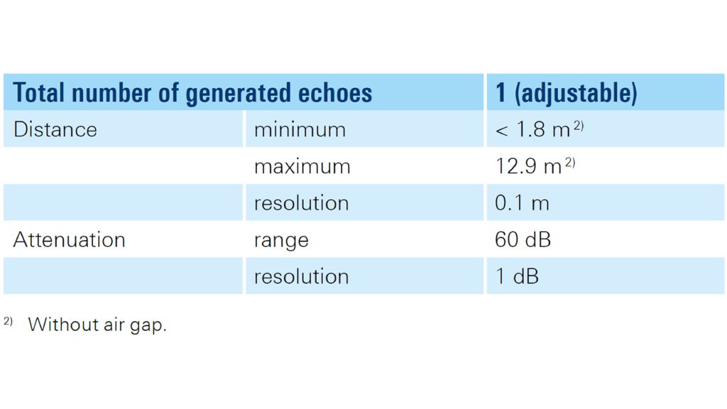
To simulate targets at a shorter range, the R&S®QAT100 can be equipped with an analog stepped delay line (ASDL) to reduce the minimum delay line. This line can simulate radar objects at very short distances of 1.8 m to 12.9 m that are challenging for radar echo generators. It also enables the standalone use of the R&S®QAT100. To test the angular resolution of your radar sensor, the radar sensor distinguishes between two targets at a given distance or a given angle.
In combination with a target simulator, the R&S®AREG800A can emulate moving targets.

Summary
Autonomous driver assistance systems urgently need reliable and high-quality data from various radar sensors that detect objects in the environment. Automotive companies and suppliers know how complicated testing these sensors in autonomous driving scenarios can be.
The R&S®QAT100 is the first fully electronically steerable antenna array that stimulates automotive radar sensors in the range from 76 GHz to 81 GHz. The modular R&S®QAT100 concept lets automotive OEMs and partners focus on developing and testing ADAS systems.
Open architecture OEMs let suppliers and service providers easily integrate the R&S®QAT100 platform into commercial 3D modeling, hardware-in-the-loop systems and existing test and simulation environments. Faster testing of automotive radar sensors across the whole value chain is possible from simple functional component validation to highly complex multitarget scenario testing.


