High readback accuracy
With integrated statistics
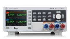
R&S®NGA100 power supplies have outstanding programming and readback accuracy to precisely measure and replicate actual device power consumption, even at low voltage and current levels.
IoT devices can have multiple sleep modes where current consumption is very low. To accurately determine these operating states, R&S®NGA100 power supplies have a low-current measurement range. Currents below 200 mA are measured with a resolution of 1 μA and an accuracy of ±(0.15 % + 25 μA).
In addition, integrated statistics show the min. and max. values for power, voltage and current.
These built-in measurements reduce the need for external multimeters and simplify the setup.