Understanding basic oscilloscope operation

Interested?

R&S®Essentials | Digital oscilloscope fundamentals

Debugging serial protocols with an oscilloscope

Author: James Lewis l Test & Measurement expert and blogger

Get ready to dive into the fascinating world of UART, I2C, (Q)SPI and CAN bus. You'll not only learn about these serial protocols but also discover how to debug them using an oscilloscope. From practical tips to real-world insights, we've prepared the basics to help you master protocol debugging.

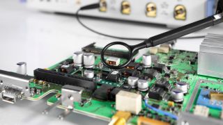
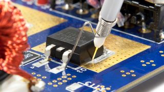
Edge computing devices can have a microcontroller (MCU) connected to sensors, actuators, buttons and displays. Most of these discrete devices communicate with the MCU using a digital protocol, such as UART, I2C or CAN. One advantage to debugging these serial protocols with an oscilloscope is that the small number of signals is easier to probe compared to the wide parallel buses of the past. With probes, oscilloscopes offer a deep set of analysis tools that would otherwise require a separate protocol analyzer. Here are some tips on how to use an oscilloscope to decode serial protocols and introductory information for the most common serial protocols.

Oscilloscope versus Logic Analyzer

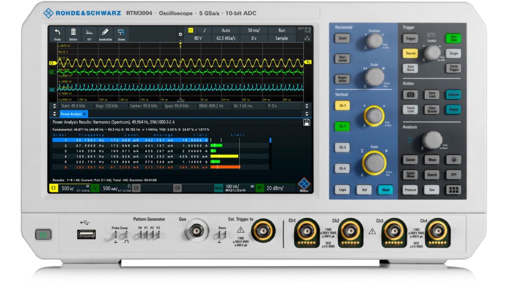
R&S®RTM3000 oscilloscope

R&S®RTM3000 oscilloscope

Key facts:

  • Bandwidth: 100 MHz to 1GHz
  • Sample rate: up to 5 Gsample/s
  • Memory depth: up to 80 Msample
  • ADC resolution: 10-bit

When looking at protocol decode, you could use an oscilloscope, logic analyzer, or dedicated protocol analyzer. But which of these tools makes the most sense? Here is a brief comparison of the three.

Logic analyzer channels are essentially digital comparators. Therefore, they can only tell you if a signal is high or low. Typical logic analyzers have at least eight channels, with some models offering 32 or more. Protocol analyzers are similar to logic analyzers but have protocol-specific hardware and software to decode the serial link.

In contrast, oscilloscopes have many bits of resolution but are typically limited to two or four channels. The increased bit-depth lets you see the analog characteristics of signals.

Fortunately, with modern oscilloscopes, there is rarely a need to choose one of these three options. Many scopes, including all Rohde & Schwarz models, offer logic channels, both analog and digital. Such oscilloscopes are called “mixed signal oscilloscopes.”

Some oscilloscopes even have protocol decode tools for serial buses! For example, the R&S®RTB2000, R&S®MXO 4 or R&S®RTO 6 have built-in protocol decode and trigger for frequently used serial protocols.

The oscilloscope especially shines when a protocol error is detected. An analog channel (or channels) sampling the bus can show you if there is an analog issue at (or around) the time of the protocol error. That situation is rarely the case with a logic analyzer.

Since so many serial protocols exist and their support varies by oscilloscope model, here are some notes and tricks for debugging circuits with the most common buses.

UART

The universal asynchronous receiver/transmitter (UART) is also sometimes called “serial.” The transmit and receive signals are wires with no discrete clock. It is point-to-point which means you usually only have two devices connected.

In some cases, UART is the simplest to debug because you only need to look at a minimum of one signal: the TX or RX. However, in practice, you generally need to see both directions to understand the communication.

UART set-up

UART set-up

Flexible framing method of UART

Flexible framing method of UART

UART has a flexible framing method. There are a variable number of start and stop bits and an optional parity bit. The data payload is typically 8-bits. Since UART is asynchronous, the host and device must agree on these parameters as well as on the baud rate. The same requirements apply to an oscilloscope during debugging.

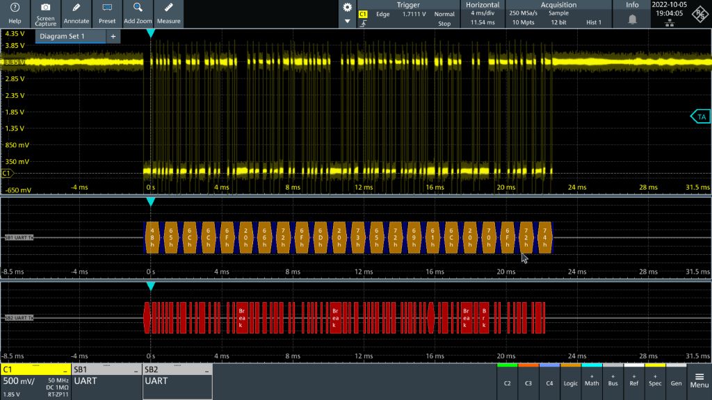
Debugging on an oscilloscope

Tip: Decoders usually let you change the baud rate post-capture. Adjust this setting if it is decoding garbage. Otherwise, it will not be able to decode (or trigger) properly.

SPI & QSPI

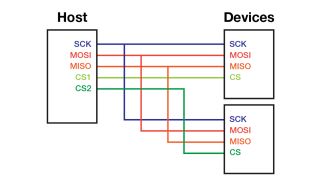
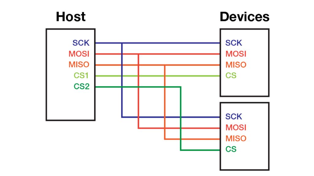
All devices share the clock

Text SPI or S-P-I is known as the “serial peripheral interface.” It works like a shift register. All devices share the clock; the main output, secondary input (MOSI) signals; and the main input, secondary output (MISO) signals. These correspond to UART's “TX” and RX.” However, they are explicit in which direction the data moves. For example, with MOSI, the data goes from host to device, and with MISO, the data goes from device to host. This makes probing the wrong signal less likely!

The SPI protocol supports multiple devices on the same bus. Each device has a chip select (CS) signal to differentiate between devices. However, designs with only one SPI device might omit (or always enable) the CS signal. Similarly, if data only goes in one direction, then only the appropriate MOSI or MISO signal needs to be connected.

The same idea holds for debugging with an oscilloscope. If only one device is on the bus, it is unnecessary to probe CS. And if data only moves in one direction, then most decoders can handle having only one probed. The clock signal, however, is always required.

What is QSPI?

A prevalent interface standard for flash memory chips is the quad SPI (QSPI) protocol. Like SPI, it has a clock, enable and data pin.

Inter-Integrated Circuit (I2C)

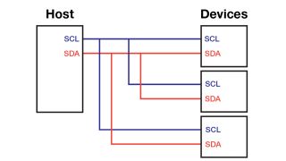
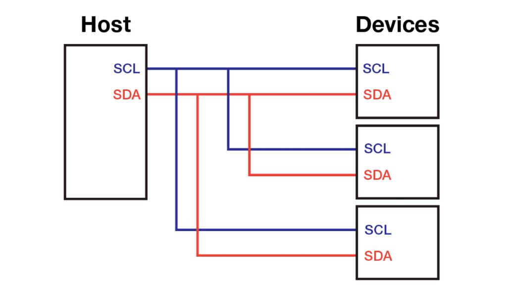
Devices share clock and data lines

The Inter-Integrated Circuit (I2C) was originally developed by Philips, which later became part of NXP. Sometimes devices that support I2C use the name “two-wire” to avoid trademark or licensing issues.

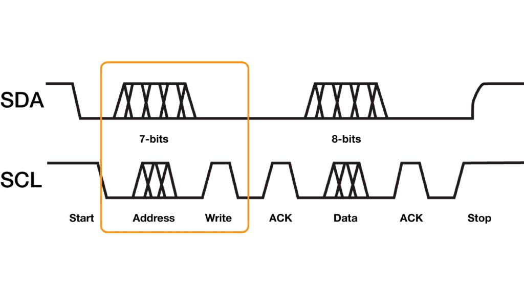
All devices on the bus share the clock and data lines, and each device must have a unique address. In general, sensors or devices that use I2C will have a base address with a few bits to set the least significant bits of their address. This technique is helpful when you have multiples of the same sensor on the bus with a minimum number of pins.

For I2C, debugging on the oscilloscope requires two channels. The clock only runs when the host is communicating with a device. So, the oscilloscope must capture both clock and data signals.

I2C: 7-bit or 8-bit (or 10-bit)

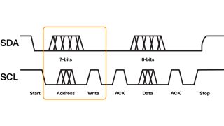
I2C addresses can be confusing because of the two different address modes: 7-bit and 10-bit. The 7-bit mode is more common, but it has a confusing feature: sometimes, it is considered an 8-bit address!

Comparison of 7-bit and 8-bit address modes

The confusion comes from the R/W bit that comes after the address. For READ transactions, the value is “1.” And for WRITE transactions, the value is “0.” So, if triggering is failing on the expected address when debugging I2C, try shifting the address one bit to the left and include the R/W value.

CAN bus

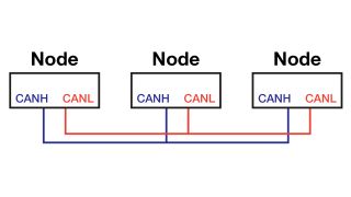
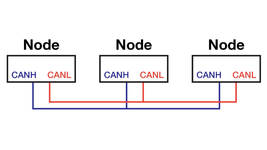
CAN bus has differential signaling

Controller area network (CAN) was developed for use in automobiles and continues to be heavily used in the transportation industry. Its differential signaling improves immunity to electrical noise, making it ideal for industrial applications.

Despite being differential, it does not require a differential oscilloscope probe in most cases. Instead, a single-ended probe on either the “CANH” or “CANL” signal is enough for an oscilloscope decoder to decode the bus.

There are two CAN 2.0 versions: base (11-bit address) and extended (29-bit address). Their data frames are slightly different in the arbitration and control fields, but otherwise, their packets are the same.

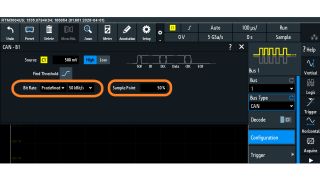
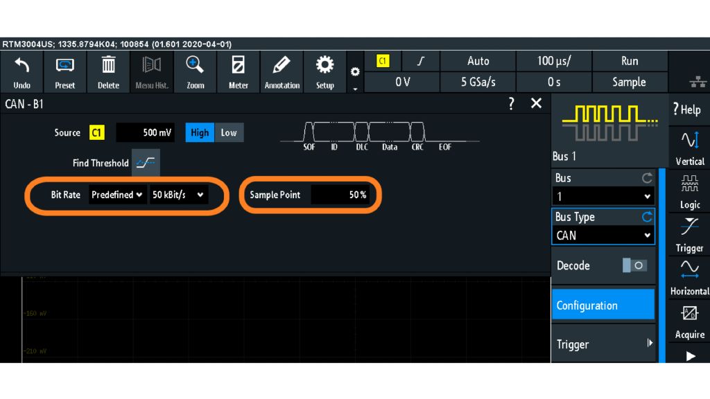
CAN decode using R&S®RTM3000

The CAN bus only uses two signal wires, neither of which is a clock. Therefore, if a decode seems garbled, try adjusting the sample point to change where the decoder samples data.

Decode versus Trigger

Decode is a post-process method that analyzes the captured waveform and decodes the protocol into a human-readable form. Typically, the decoded data is available as an overlay on the waveform display or as a table. (Some oscilloscopes, like the R&S RTE, RTO6 and RTP, also offer additional analysis tools like bus utilization.) Oscilloscopes with deep memory can capture long periods and then search to find events of interest (or how often those events occur). This technique is primarily a “software” approach.

Trigger, however, happens within the oscilloscope's trigger system. A protocol trigger continuously monitors the serial bus to determine when events occur. For example, two common triggers are an I2C address or an error condition (NAK or Parity error). Trigger options are generally limited to a few protocol-specific transactions and may also be limited to the bit depths of either address, data or payload. This technique is primarily a "hardware" approach.

Sometimes, oscilloscopes combine the two techniques: the trigger system may "auto-trigger" while the protocol decoder finds the event of interest and then places it in the center of the screen. If your oscilloscope “misses” certain events, check the manual to determine which trigger conditions are “hardware”-based and which are “software”-based.

Summary

  • Most edge computing devices communicate with the MCU using a digital protocol, such as UART, SPI, I2C or CAN.
  • Oscilloscopes offer a wide range of tools to decode serial protocols.
  • Some oscilloscopes even have protocol decode tools for serial buses.
  • UART has no discrete clock and is point-to-point, meaning that only two devices are connected.
  • SPI works like a shift register, and all devices share the clock, MOSI signals and MISO signals.
  • For I2C, debugging requires two channels. The clock only runs when the host is communicating with a device, so the oscilloscope must capture both clock and data signals.
  • Despite being differential, CAN does not usually require a differential oscilloscope probe. Instead, a single-ended probe on either the "CANH" or "CANL" signal is enough for an oscilloscope decoder to decode the bus.
  • All Rohde & Schwarz oscilloscopes have optional serial protocol options. Available triggers vary based on the oscilloscope model and its bandwidth capabilities. However, most offer support for the basic serial protocols listed here.
  • For general-purpose debugging with typical serial protocols, look into the RTB2000 or RTM3000. For protocols faster than 480 Mbit/s, look into the MXO4 (1.5 GHz), RTO, and RTP oscilloscopes.

Curious to learn more about test fundamentals?

Sign up for our newsletter

Also interesting for you