Written by Albert Huang | July 15, 2020

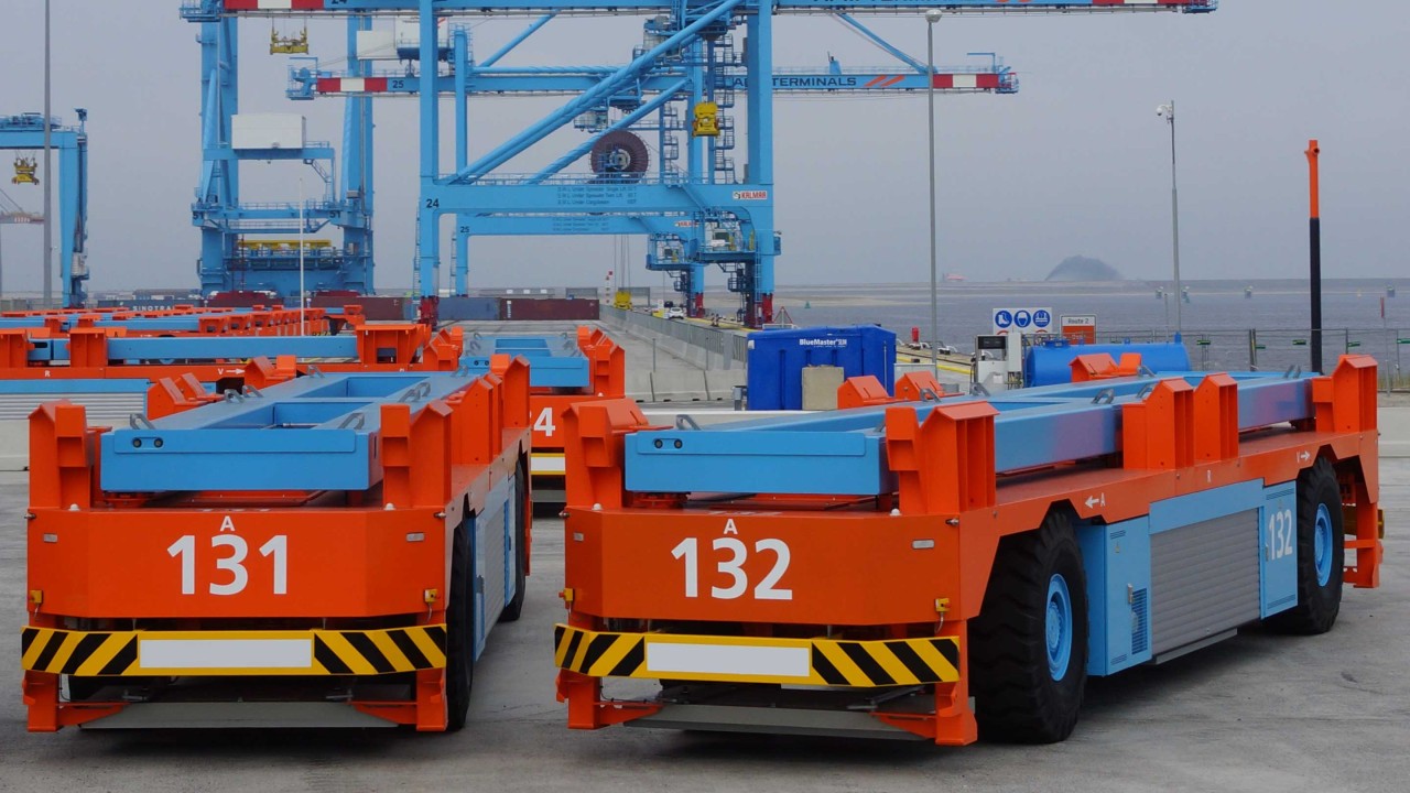
Rohde & Schwarz mobile network testing (MNT) assisted a tier-1 network operator and infrastructure vendor during initial trials of a 5G network in a port terminal in Singapore. 5G is expected to provide significant improvements in the area of autonomous driving since a key benefit of 5G is ultra-reliable low latency communications (URLLC). Full automation and adoption of URLLC are critical to ports’ competitiveness, including increased safety, reliability, and efficiency.
As all automated guided vehicles (AGVs) for port operations are based on real-time connectivity, AGVs are no less than connected cars driving autonomously. Continuous high-speed data connectivity is required for real-time map updates on which the AGVs on their pre-defined paths depend.
5G measurement setup in a challenging environment
The port in question posed many challenges to the network operator and infrastructure supplier, and the typical port environment requires measurement equipment that is flexible and reliable. Ports are dynamic environments; most areas have restricted access where coverage is challenging; and high temperatures and high humidity along with the mechanical impact sustained to equipment demand solutions that are adaptable and robust.
For the measurements, R&S®ROMES4 and the R&S®TSMA6 scanner were used. R&S®ROMES4 supports connection to both scanners and 5G devices (smartphones, routers, and modules) simultaneously, thereby reducing the staff-hours required for in-field 5G measurements while overcoming the challenges faced by the dynamic port environment.
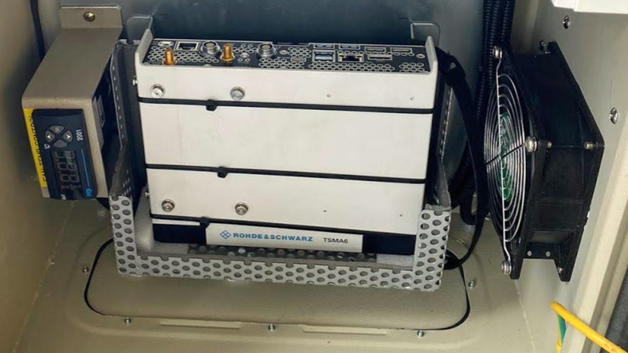
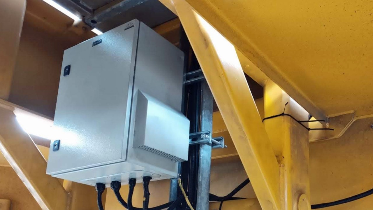
The R&S®TSMA6 scanner was installed inside a target AGV, and a remotely controlled connection to the scanner was established. Measurements in different areas of the terminal were initiated to observe and analyze the RF performance of the network in real time.


With perspectives from both the passive scanner and the active user equipment (UE) used by the AGV for 5G connectivity, we could quickly analyze the site and troubleshoot or optimize it immediately. Not a simple scenario given that stacks of containers and heavy machinery, such as busy prime mover trucks or RTG cranes, are typical for port terminals; hence, safety is paramount at all times.
Concerning the RF environment, at street level, it is non-conducive since metallic objects are predominant. This means propagation characteristics and link budgets need to be calculated carefully, and RF coverage measurements are necessary for a correct assessment of the actual air interface.
5G measurements: differences in FR1 and FR2
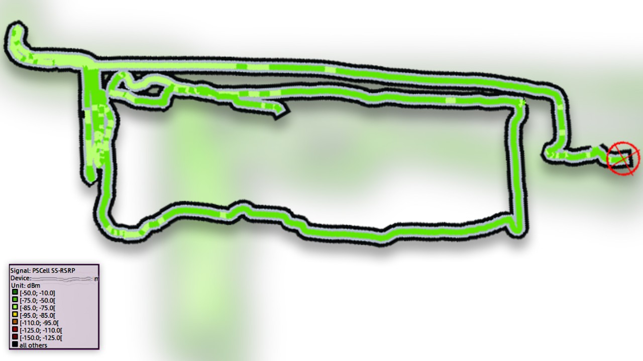
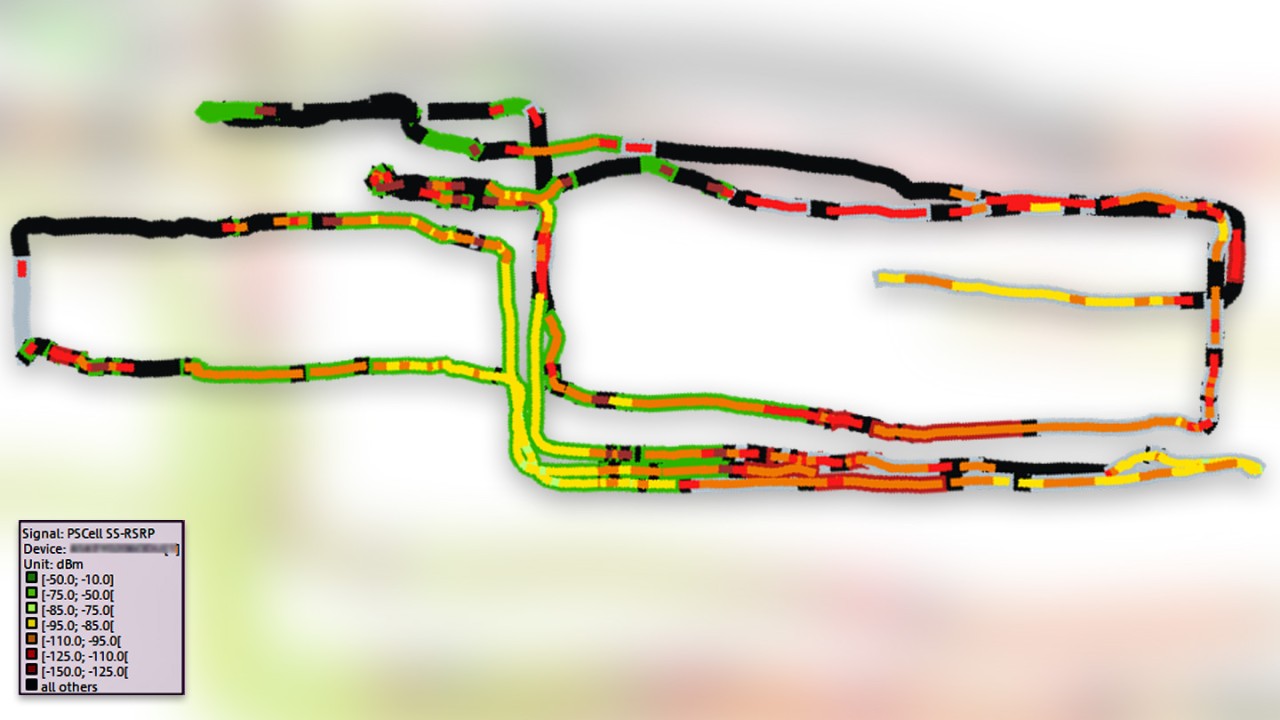
During the measurement, the 5G device was connected to R&S®ROMES4, and the primary secondary cell (PS) SS-RSRP was measured for both FR1 and FR2 5G EN-DC bands. As expected, the FR1 bands far outperformed the RF coverage of the high-frequency FR2 bands (compare maps below). Due to the high losses in FR2, we observed black areas or blind spots, especially in areas where stacked metal containers blocked the antenna’s line-of-sight (LOS).


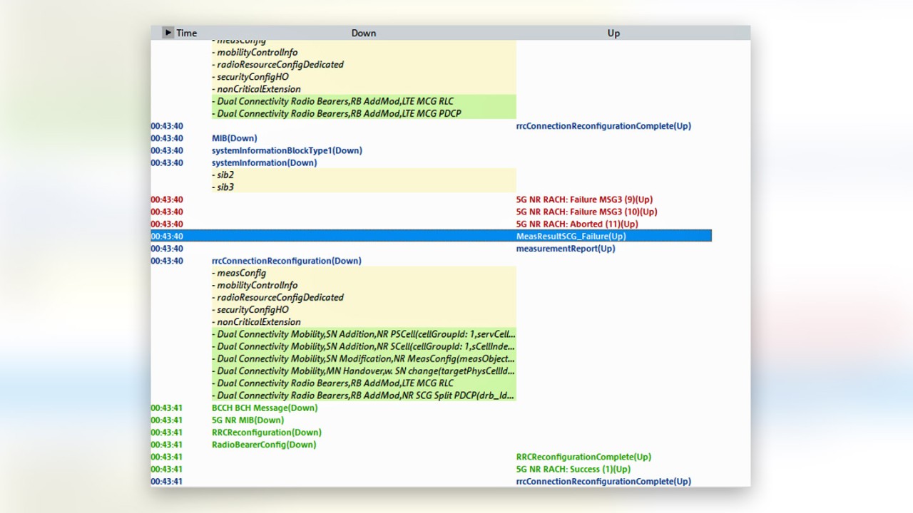
We further observed that when the AGV enters an area with blocked LOS of the FR2 antenna, the UE attempts to establish a connection to the 5G base station but fails to do so because of the unfavorable conditions.
In the screenshot below, we see a secondary carrier group (SCG) failure (blue row), which is an example of failing to connect to the FR2 network. The SCG failure is a result of RACH failures, which are indicated in the message flow of R&S®ROMES4.
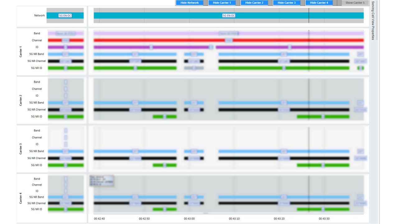
Once the AGV steered clear of the obstacle, an almost instantaneous RRC reconfiguration success occurred. The UE successfully connected to the secondary group in its entirety, with four multiple carriers successfully connected to the UE in FR2. The overview in R&S®ROMES4 shows the different bands, carriers, and beams in rows and color-coded.
Valuable insights into the air interface
These measurements offered valuable insights into the air interface at typical port terminals. At this particular port, the 5G network was further optimized to better suit the terminal operating AGVs on pre-defined routes. Moreover, the measurement results allow for critical decision-making about increasing the number of sites, adjusting the antenna direction to better suit the AGV path, or regulating the transmission power of the 5G base station.
Once the network is set up, the next step is to ensure that it is functional. Monitoring is now critical to detect any issues from the network to the UE that could result in failures or performance degradations. We also have the first measurements to address 5G monitoring, which we’ll share in a future post. So, stay tuned for more!


