Understanding UART

Interested?

R&S®Essentials | Digital oscilloscope and probe fundamentals

Understanding UART

What is UART?

UART stands for universal asynchronous receiver / transmitter and defines a protocol, or set of rules, for exchanging serial data between two devices. UART is very simple and only uses two wires between transmitter and receiver to transmit and receive in both directions. Both ends also have a ground connection. Communication in UART can be simplex (data is sent in one direction only), half-duplex (each side speaks but only one at a time), or full-duplex (both sides can transmit simultaneously). Data in UART is transmitted in the form of frames. The format and content of these frames is briefly described and explained.

Data in UART is transmitted in the form of frames

Where is UART used?

UART was one of the earliest serial protocols. The once ubiquitous serial ports are almost always UART-based, and devices using RS-232 interfaces, external modems, etc. are common examples of where UART is used.
In recent years, the popularity of UART has decreased: protocols like SPI and I2C have been replacing UART between chips and components. Instead of communicating over a serial port, most modern computers and peripherals now use technologies like Ethernet and USB. However, UART is still used for lower-speed and lower-throughput applications, because it is very simple, low-cost and easy to implement.

Timing and synchronization of UART protocols

One of the big advantages of UART is that it is asynchronous – the transmitter and receiver do not share a common clock signal. Although this greatly simplifies the protocol, it does place certain requirements on the transmitter and receiver. Since they do not share a clock, both ends must transmit at the same, pre-arranged speed in order to have the same bit timing. The most common UART baud rates in use today are 4800, 9600, 19.2K, 57.6K, and 115.2K. In addition to having the same baud rate, both sides of a UART connection also must use the same frame structure and parameters. The best way to understand this is to look at a UART frame.

UART frame format

UART frames contain start and stop bits, data bits, and an optional parity bit, which will be explained below.

As with most digital systems, a “high” voltage level is used to indicate a logical “1” and a “low” voltage level is used to indicate a logical “0”. Since the UART protocol doesn’t define specific voltages or voltage ranges for these levels, sometimes high is also called “mark” while low is called “space”. Note that in the idle state (where no data is being transmitted), the line is held high. This allows an easy detection of a damaged line or transmitter.

Start and stop bits

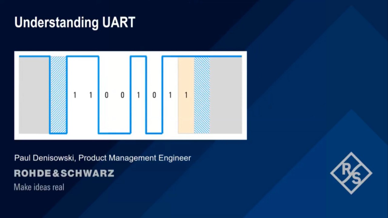
Because UART is asynchronous, the transmitter needs to signal that data bits are coming. This is accomplished by using the start bit. The start bit is a transition from the idle high state to a low state, and immediately followed by user data bits.
After the data bits are finished, the stop bit indicates the end of user data. The stop bit is either a transition back to the high or idle state or remaining at the high state for an additional bit time. A second (optional) stop bit can be configured, usually to give the receiver time to get ready for the next frame, but this is uncommon in practice.

Data bits

The data bits are the user data or “useful” bits and come immediately after the start bit. There can be 5 to 9 user data bits, although 7 or 8 bits is most common. These data bits are usually transmitted with the least significant bit first.

Example:
If we want to send the capital letter “S” in 7-bit ASCII, the bit sequence is 1 0 1 0 0 1 1. We first reverse the order of the bits to put them in least significant bit order, that is 1 1 0 0 1 0 1, before sending them out. After the last data bit is sent, the stop bit is used to end the frame and the line returns to the idle state.

  • 7-bit ASCII ‘S’ (0x52) = 1 0 1 0 0 1 1
  • LSB order = 1 1 0 0 1 0 1

Start and stop bits

Data bits

Parity bit

A UART frame can also contain an optional parity bit that can be used for error detection. This bit is inserted between the end of the data bits and the stop bit. The value of the parity bit depends on the type of parity being used (even or odd):

  • In even parity, this bit is set such that the total number of 1s in the frame will be even.
  • In odd parity, this bit is set such that the total number of 1s in the frame will be odd.

Example:
Capital “S” (1 0 1 0 0 1 1) contains a total of three zeros and 4 ones. If using even parity, the parity bit is zero because there already is an even number of ones. If using odd parity, then the parity bit has to be one in order to make the frame have an odd number of 1s.
The parity bit can only detect a single flipped bit. If more than one bit is flipped, there’s no way to reliably detect these using a single parity bit.

Parity bit example

Understanding UART

Watch our video "Understanding UART" to learn more

This video explains the technical overview of the UART (universal asynchronous receiver/transmitter) serial protocol, including a description of the frame structure and the significance of each frame bit.

Summary

  • UART stands for universal asynchronous receiver / transmitter and is a simple, two-wire protocol for exchanging serial data.
  • Asynchronous means no shared clock, so for UART to work, the same bit or baud rate must be configured on both sides of the connection.
  • Start and stop bits are used to indicate where user data begins and ends, or to “frame” the data.
  • An optional parity bit can be used to detect single bit errors.
  • UART is still a widely used serial data protocol but has been replaced in some applications by technologies such as SPI, I2C, USB, and Ethernet in recent years.

Do you have any questions about UART or other serial protocols? Our experts will help you.