Doherty Implementations – The Zeroth Embodiment

Measurement-aided Doherty amplifier design - chapter 2

Amplifier starting point realization

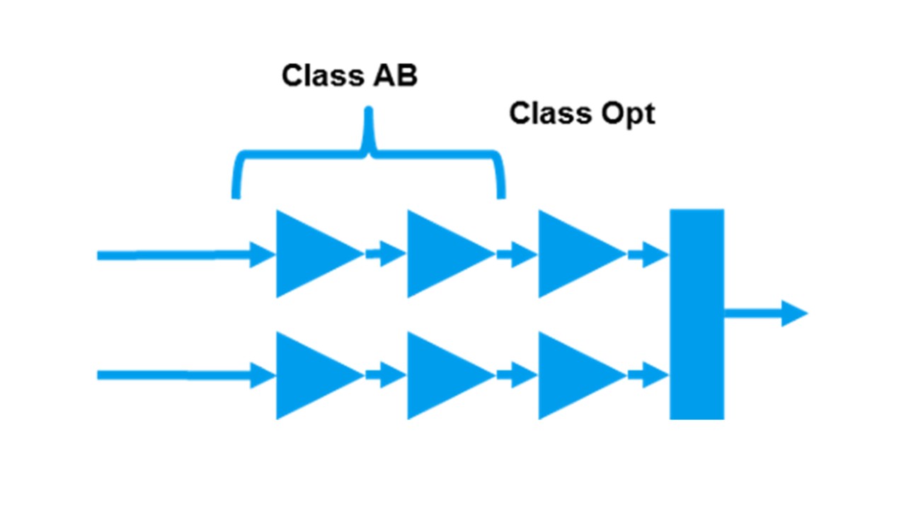
Arguably, the most common (and often quickest) starting point for Doherty amplifier realization comprises:

  • A fixed RF input power splitter
  • A Main and Auxiliary amplifier, differently biased (e.g. using “Class AB” and “Class C”)
  • A “Doherty combiner”, made from a quarter-wavelength transmission line.
  • In most applications, this architecture does not provide sufficient power gain, at least not from a single, final stage. Therefore, additional gain stages are cascaded ahead of the input.

Criticisms of this most commonly used technique might include:

  • No method for compensation gain-phase variations (in any domain), after design freeze.
  • Both efficiency and output power are traded-off because of the bias class (in effect, an open loop analog circuit, the class C bias, is driving this)
  • Efficiency enhancement of only a single stage, in a multistage cascade, limits the performance improvement, especially as gain diminishes at higher frequencies

Ask the expert

Gareth Lloyd

Gareth Lloyd

Gareth Lloyd graduated from the University of Leeds in 1994 with a degree in Electronic & Electrical Engineering. Gareth has worked in various engineering and management roles, in different industries, for major companies including Ericsson, Huawei, ZTE, TriQuint and Andrew Corporation. Gareth joined Rohde & Schwarz in 2015, as a Senior Expert. His primary work focus is performance differentiated radio front-ends (RFFE).

Ask Gareth

Related chapters

Request information

Do you have questions or need additional information? Simply fill out this form and we will get right back to you.

Marketing de permission

Votre demande a bien été envoyée ! Nous vous contacterons dans les plus brefs délais.
An error is occurred, please try it again later.