


Key Facts
- Bandwidth: 200 MHz to 1 GHz
- Sample rate: up to 5 Gsample/s
- Memory depth: up to 1 Gsample
- ADC resolution: 10-bit
- Display: 10.1’’ capacitive touchscreen
Commençant à 6 990 CHF


Key Facts
Commençant à 6 990 CHF
Designed with top class signal integrity and responsive ultra-deep memory, the R&S®RTA4000 brings the power of 10 to a new level. The Rohde & Schwarz designed 10-bit ADC plus best-in-class noise and memory depth for sharp waveforms, more accurate measurements and confidence when faced with unexpected measurement challenges.
See small signal details in the presence of large signals
The R&S®RTA4000 has a customized Rohde & Schwarz 10-bit A/D converter and is a four-fold improvement over conventional 8-bit A/D converters. The increased resolution results in sharper waveforms with more signal details that would otherwise be missed. One example is the characterization of switched-mode power supplies. The voltage across the switching device must be determined during the on/off times within the same acquisition.

10-bit A/D converter
10-bit A/D converter uncovers even small signal details and ensures vertical resolution four times higher than traditional oscilloscopes.
100 Mpoint standard and 200 Mpoint interleaved
The R&S®RTA4000 has top-class memory depth of 100 Mpoints per channel and 200 Mpoint in interleaved mode. This is ten times more than similar oscilloscopes in the same instrument class. Users can capture longer acquisition sequences even at high sampling rates for more analysis results, such as when examining transients in switched-mode power supplies.

100 Msample standard memory
Capture and analyze pulsed and burst signals over a long period with up to 200 Mpoint standard acquisition memory
Segmented memory: 1000 Mpoint with history function
The R&S®RTA-K15 option with deep, segmented memory analyzes signal sequences over a long observation period. Protocol-based signals with communications gaps such as I²C or SPI can be captured over several seconds or minutes. The variable segment sizes enable optimal utilization of the 1000 Mpoint memory. In history mode, previous acquisitions in the maximum segmented memory depth of 1000 Mpoint can be used for further analysis.

1000 Mpoint segmented memory
Capture the longest time periods with top-class 1000 Mpoint memory
16 additional digital channels
The R&S®RTA-B1 option turns every R&S®RTA4000 into an intuitive MSO with 16 additional digital channels. The oscilloscope captures and analyzes signals from the analog and digital components of an embedded design - synchronized and time correlated to each other. The delay between A/D converter input and output can be conveniently determined with cursor measurements.

Four-bit DAC signal change.
The R&S®RTA4000 captures and analyzes analog and digital signals that are synchronized and time-correlated with each other.
Generate analog and digital stimuli
The R&S®RTA-B6 waveform and pattern generator for up to 50 Mbit/s can be used in educational settings and prototype hardware implementation. Apart from the common sine, square/pulse, ramp and noise waveforms, it outputs arbitrary waveforms and 4-bit signal patterns. Waveforms and patterns can be imported as CSV files or copied from oscilloscope waveforms. Predefined patterns include. I2C, SPI, UART and CAN/LIN.

Waveform and pattern generator
In addition to common sine, square/pulse, ramp and noise waveforms, it outputs user-defined waveforms and 4-bit signal patterns.
Measure and display electrical potential
The R&S®RTA4000 features a 3-digit voltmeter (DVM) and 6-digit frequency counter on each channel for simultaneous measurements. Standard measurement functions include DC, AC+DC (RMS) and AC (RMS).

Digital voltmeter
The 3-digit voltmeter measures and displays the electrical potential difference between two points in an electric circuit.
Difficult-to-find faults often result from the interaction between time and frequency signals. The R&S®RTA4000 FFT function is activated at the push of a button or by simply entering the center frequency and span. The high-performance FFT function in the R&S®RTA4000 oscilloscope can be used to analyze signals with up to 128k points. Other practical tools include cursor measurements and autoset in frequency domain.

FFT of a square wave
The high-performance FFT functionality analyzes signals up to 128k points.
Mask tests quickly reveal whether a specific signal lies within defined tolerance limits. Masks assess the quality and stability of a DUT based on statistical pass/fail evaluations. Signal anomalies and unexpected results are quickly identified. When the mask is violated, the measurement stops. Each violation generates a pulse output at the AUX-OUT connector on the R&S®RTA4000. This pulse output can be used to trigger actions in the measurement setup.

Mask test with result statistics
The pass/fail evaluation assesses DUT quality and stability.
See power signal details with up to 10-bit resolution
Even the smallest details of a high dynamic signal are important to power measurements. RDS (on) verification for a MOSFET is one example. The high ADC resolution of R&S®RTA4000 oscilloscopes increases vertical resolution up to 10 bits. Previously unseen signal details are revealed and measurable. The RDS(on) example shows how the slope of the drain-to-source-voltage can be measured while the switch is closed.

Power analysis
Analyze input, output and transfer functions of switched-mode power supplies
| Vertical system | ||
| Analog channels | 4 | |
| Digital channels (opt.) | 16 | |
| Bandwidth (-3 dB) | R&S®RTA4004 (with R&S®RTA-B24x options) | 200 MHz, 350 MHz, 500 MHz, 1 GHz |
| Rise time | R&S®RTA4004 (with R&S®RTA-B24x options) | 1.75 ns, 1 ns, 700 ps, 350 ps |
| Input impedance | 50 Ω ± 1,5% (meas.), 1 MΩ ± 1 % (meas.) || 14 pF ± 1 pF (meas.) | |
| Input sensitivity | max. bandwidth in all range | at 1 MΩ: 500 μV/div to 10 V/div at 50 Ω: 500 μV/div to 1 V/div |
| ADC resolution | 10 bit, up to 16 bit with high resolution decimation | |
| DC gain accuracy | offset and position = 0, maximum operating temperature change of ±5°C after self-alignment | input sensitivity > 5 mV/div: ±1 % of full scale input sensitivity ≤ 5 mV/div to ≥ 1 mV/div: ±1.5 % of full scale input sensitivity < 1 mV/div: ±2.5 % of full scale |
| Acquisition system | ||
| Real-time sampling rate | 2.5 Gsample/s; 5 Gsample/s, interleaved | |
| Acquisition memory | 100 Mpoint (200 Mpoint, interleaved); 1 Gsample segmented memory |
|
| Max. acquisition rate | 64 000 waveforms/s (2 000 000 in fast segmented memory mode) |
|
| Horizontal system | ||
| Timebase range | selectable between 0.5 ns/div and 500 s/div | |
| Accuracy (after delivery/calibration) | ±0.5 ppm | |
| Channel-to-channel skew | < 200 ps (meas.) | |
| Channel deskew | ±500 ns | |
| Trigger system | ||
| Standard trigger types | edge, width, video (PAL, NTSC, SECAM, PAL-M, SDTV 576i, HDTV 720p, HDTV 1080i, HDTV 1080p), pattern, line, serial bus | |
| Optional trigger types | I2C, SPI, UART/RS-232/RS-422/RS-485, CAN/LIN, audio (I2S),ARINC 429, MIL-STD-1553 | |
| Trigger sensitivity | with DC, AC, LF reject, noise reject 1 GHz, 500 MHz, 350 MHz > 2.2 mVpp input sensitivity + 1 div (nom.) (input sensitivity: [mV/div]) 200 MHz, 100 MHz > 1.5 mVpp input sensitivity + 0.8 div (nom.) (input sensitivity: [mV/div]) 20 MHz > 0.6 mVpp input sensitivity + 0.4 div (nom.) (input sensitivity: [mV/div]) with HF reject all input sensitivities 1 div (meas.) | |
| Analysis and measurement functions | ||
| Automatic measurements | 32 | |
| Cursor measurements | 4 | |
| Waveform mathematics | Five equations math-on-math functions (addition, subtraction, multiplication, division, square, square root, abs. value, reciprocal, inverse, common log,, natural log., derivative, integral, low pass, high pass, track unipolar + bipolar on period, frequency, pulse width, duty cycle) | |
| Mask testing | ||
| Mask definition | elementary (tolerance mask around the signal) | |
| History and segmented memory | ||
| Number of segments | up to 87 380 | |
| Protocol trigger and decode | ||
| Supported protocols | I2C, SPI, UART/RS-232/RS-422/RS-485, CAN, LIN, I2S, MIL-STD-1553, ARINC429 | |
| Waveform generator | ||
| Resolution | 14 bit | |
| Sample rate | 250 Mpoint/s | |
| Amplitude | high Z; 50 Ω | 20 mV to 10 V (Vpp); 10 mV to 5 V (Vpp) |
| DC offset | high Z; 50 Ω | ±5 V; ±2.5 V |
| Arbitrary | max. 10 Mpoint/s; 32k point | |
| Logic analyzer (MSO) functionality | ||
| Digital input channels | 16 | |
| MSO memory depth | two logic probes: 100 Mpoint for every channel one logic probe: 200 Mpoint for every channel |
|
| MSO Bandwidth | 400 MHz (meas.) | |
| MSO sampling rate | 2.5 Gsample/s; 5 Gsample/s, interleaved | |
| MSO input impedance | 100 kΩ ± 2 % || ~4 pF (meas.) at probe tips | |
| Parallel buses | up to 4 | |
| General data | ||
| Dimensions | W × H × D | 390 mm × 220 mm × 152 mm (15.4 in × 8.66 in × 5.98 in) |
| Weight | 3.3 kg (7.3 lb) | |
| Display | 10.1" WXGA TFT color display (1280 × 800 pixel) | |
| Interfaces | USB host with MTP, USB device, LAN, powerful web server for remote display and operation | |
| Operating system | Embedded | |

Numéro de commande 1335.7823.02
Mixed signal option: 400 MHz
Turns R&S®RTA4000 oscilloscopes into fast, precise and easy-to-use mixed signal oscilloscopes (MSO).

Numéro de commande 1335.7830.02
Arbitrary waveform generator
Adds a 25 MHz signal generator and a 4-bit pattern generator to your R&S®RTA4000 oscilloscopes.
Numéro de commande 1335.7846.02
Bandwidth upgrade of the R&S®RTA4004 to 350 MHz bandwidth
Numéro de commande 1335.7852.02
Bandwidth upgrade of the R&S®RTA4004 to 500 MHz bandwidth
Numéro de commande 1335.7869.02
Bandwidth upgrade of the R&S®RTA4004 to 1 GHz bandwidth

Numéro de commande 1335.7681.02
I²C/SPI serial triggering and decoding
Triggering and decoding of I²C and 2-wire, 3-wire or 4-wire SPI buses

Numéro de commande 1335.7698.02
UART/RS-232/RS-422/RS-485 serial triggering and decoding
Triggering and decoding of UART based protocols and RS-232, RS-422 as well as RS-485 buses

Numéro de commande 1335.7717.02
CAN/LIN serial triggering and decoding
Triggering and decoding of CAN and LIN interfaces

Numéro de commande 1335.7723.02
I²S/LJ/RJ/TDM triggering and decoding
Triggering and decoding of I²S buses

Numéro de commande 1335.7730.02
MIL-1553 serial triggering and decoding
Triggering and decoding of MIL-STD-1553 buses

Numéro de commande 1335.7746.02
ARINC 429 serial triggering and decoding
Triggering and decoding of ARINC 429 buses

Numéro de commande 1335.7769.02
Power analysis
When analyzing power electronics, the input and output and the internal transfer function of the component have to be characterized. The power analysis option provides the necessary measurement functions, including inrush current, output spectrum and safe operating area (SOA).

Numéro de commande 1335.7975.02
Frequency Response Analysis (Bode plot)
The R&S®RTA-K36 frequency response analysis (Bode plot) option lets you perform low-frequency response analysis on your oscilloscope easily and quickly. It characterizes the frequency response of a variety of electronic devices, including passive filters and amplifier circuits. For switch mode power supplies, it measures the control loop response and power supply rejection ratio.

Numéro de commande 1335.7981.02
Spectrum analysis and spectrogram
The spectrum analysis option enhances the powerful FFT capability of R&S®RTA4000 oscilloscopes with spectrogram display.

Numéro de commande 1333.1728.02
Front cover
Protects the front of the R&S®RTB2000, R&S®RTM3000 or R&S®RTA4000

Numéro de commande 1333.1734.02
Soft bag
Stores the R&S®RTB2000, R&S®RTM3000 or R&S®RTA4000 oscilloscope and accessories

Numéro de commande 1335.9290.02
Transit case with wheels for R&S®RTB

Numéro de commande 1335.7875.02
Accessory case for probes and small parts for all Rohde and Schwarz oscilloscopes

Numéro de commande 1338.0007.02
Probe adapter
Enables Tek’s TekProbe-BNC level 2 probes to connect to Rohde & Schwarz probe interface

Numéro de commande 1333.1711.02
19" rackmount adapter for R&S®RTB2000, R&S®RTM3000 or R&S®RTA4000 with 5HU

Numéro de commande 1333.2401.02
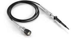
Passive probe, 500 MHz, 10:1
Numéro de commande 1409.7550.00
Passive probe, 500 MHz, 10:1

Numéro de commande 1333.1370.02
Passive probe, 38 MHz, 1:1

Numéro de commande 1333.0815.02
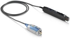
Active single-ended probe, 1 GHz, BNC interface

Numéro de commande 1418.7007.02
Active single-ended probe, 1 GHz, Rohde & Schwarz probe interface
Numéro de commande 1410.4080.02
Active single-ended probe, 1 GHz, R&S®ProbeMeter, Rohde & Schwarz probe interface

Numéro de commande 1410.3502.02
Active single-ended probe, 1.5 GHz, R&S®ProbeMeter, Rohde & Schwarz probe interface

Numéro de commande 1410.4715.02
Active differential probe, 1 GHz, Rohde & Schwarz probe interface
Numéro de commande 1410.4409.02
Active differential probe, 1.5 GHz, Rohde & Schwarz probe interface

Numéro de commande 1800.5006.02
Power rail probe, 2 GHz, R&S®ProbeMeter, Rohde & Schwarz probe interface
2.0 GHz, 1:1, 50 kΩ, R&S probe interface

Numéro de commande 1333.0873.02
250 MHz passive high voltage probe

Numéro de commande 1409.7720.02
400 MHz passive high voltage probe
Numéro de commande 1409.7737.02
400 MHz passive high voltage probe

Numéro de commande 1800.2307.02
200 MHz High voltage differential probe
Numéro de commande 1800.2107.02
100 MHz High voltage differential probe
Numéro de commande 1800.2207.02
200 MHz High voltage differential probe
Numéro de commande 1800.2007.02
100 MHz High voltage differential probe

Numéro de commande 1333.0850.02
AC/DC 20 kHz current probe

Numéro de commande 1333.0844.02
100 kHz current probe

Numéro de commande 1409.8204.02
2 MHZ current probe

Numéro de commande 1409.7750K02
10 MHZ current probe

Numéro de commande 1409.8210.02
10 MHZ Current probe

Numéro de commande 1409.8227.02
50 MHZ Current probe

Numéro de commande 1409.7766K02
100 MHZ current probe
Numéro de commande 1409.8233.02
100 MHZ current probe

Numéro de commande 1409.7772K02
120 MHz current probe

Numéro de commande 1801.4932.02
120 MHz current probe

Numéro de commande 1147.2736.02
E and H near-field probe set

Numéro de commande 1333.0721.02
400 MHz logic probe

Numéro de commande 1409.7789.02
Power supply for probes
Power supply for R&S®RT-ZC10/20/30 probes, +/-12V DC, +/-2.5A

Numéro de commande 1410.4744.02
External attenuator
10:1, 2.0 GHz, 1.3 pF, 60 V DC, 42 V AC (peak) for R&S®RT-ZD20/30 probes. Included in R&S®RT-ZD10.

Numéro de commande 1800.0004.02
Power deskew fixture
Deskew fixture for voltage and current probes for power measurements; includes USB 2.0 cable for power supply

Numéro de commande 1326.3641.02
3D probe positioner
3D positionier with central tensioning knob for easy clamping and positioning of probes (span width: 200 mm, clamping range: 15 mm)

Numéro de commande 1335.7775.02
Application bundle (R&S®RTA-K1, -K2, -K3, -K5, -K6, -K7, -K31, -K36, -K37 and -B6)
Application bundle contains triggering and decoding I²C/SPI (R&S®RTA-K1), UART/RS-232/RS-422/RS-485 (R&S®RTA-K2) and CAN/LIN (R&S®RTA-K3), I²S (R&S®RTA-K5), MIL-1553 (R&S®RTA-K6), ARINC429 (R&S®RTA-K7), spectrum analysis and spectrogram (R&S®RTA-K37), power analysis (R&S®RTA-K31), frequency response analysis (R&S®RTA-K36), arbitrary generator (R&S®RTA-B6) for R&S®RTA4000 models
Numéro de commande 1335.7998.02
Application bundle (R&S®RTA-K1, -K2, -K3, -K5, -K6, -K7, -K31, -K36, -K37 and -B6)
Application bundle contains triggering and decoding I²C/SPI (R&S®RTA-K1), UART/RS-232/RS-422/RS-485 (R&S®RTA-K2) and CAN/LIN (R&S®RTA-K3), I²S (R&S®RTA-K5), MIL-1553 (R&S®RTA-K6), ARINC429 (R&S®RTA-K7), power analysis (R&S®RTA-K31), frequency response analysis (R&S®RTA-K36), spectrum analysis and spectrogram (R&S®RTA-K37), arbitrary generator (R&S®RTA-B6) for R&S®RTA4000 models * ONLY distributed in North America
Produits associés
Manufacturer's recommended retail price (MSRP). The price shown does not include VAT. Prices and offers are only intended for entrepreneurs and not for private end consumers.
You may use the electronic signature via DocuSign to submit your information to enroll with the Rohde & Schwarz Customer Delegated Administration program. DocuSign processes the information provided according to their . The minimum system requirements for using the DocuSign system may change over time. The current system requirements are found
Termes & Conditions du tirage au sort relatif aux 10 ans des oscilloscopes Rohde & Schwarz
1. Le tirage au sort “10 years Rohde & Schwarz oscilloscopes” est organisé par Rohde & Schwarz GmbH & Co. KG, Mühldorfstraße 15, 81671 Munich, Allemagne, Tel. +49 89 41 29 0 (référencé ici par “R&S").
2. Tous les participants peuvent s'inscrire au tirage au sort du 01 janvier 2020 au 31 décembre 2020 avec leur nom, le nom de leur entreprise et leur courriel professionnel.
3. La participation est gratuite et ne dépend pas de l'achat de biens ou de services.
4. Le tirage au sort est uniquement ouvert aux entités juridiques et seules les personnes morales peuvent gagner les prix. Une personne physique n'est pas autorisée à participer en son nom propre et pour son propre compte, mais en tant que représentant d'une entité juridique en remplissant le formulaire de participation au nom et pour le compte de l'entité juridique.
5. Les prix à gagner sont 1 des 10 R&S®RTB2000 au cours de la période allant du 1 janvier 2020 au 31 décembre 2020 :
Prix : 1x oscilloscope numérique R&S®RTB2000
6. Le tirage au sort aura lieu au siège social de Rohde & Schwarz, Muehldorstrasse 15, 81671 Munich. Les gagnants des prix seront informés par courriel sous 5 jours ouvrés.
7. Le représentant autorisé de l'entité juridique devra informer Rohde & Schwarz qu'il accepte le prix. En cas de refus d'acceptation, ou sans aucune réponse dans les deux semaines, un nouveau gagnant sera tiré au sort. Si aucun gagnant ne se manifeste sous quatre semaines, le tirage au sort prend fin et le prix est perdu.
8. Les employés R&S et les membres de leurs familles, ainsi que toute personne participant au processus du tirage au sort et les membres de leurs familles sont exclus du formulaire de participation.
9. Aucun équivalent en argent ou échange de prix n'est autorisé. Les prix ne sont pas transférables. Tous les impôts, les prélèvements, les droits, les taxes et toutes autres charges perçus dans le pays du participant sont à la charge du participant.
10. Les données personnelles seront traitées uniquement dans le cadre de ce tirage au sort et supprimées quatre semaines après celui-ci, sauf indication contraire.
11. Tout participant qui ne respecte pas ces Termes & Conditions peut être disqualifié par Rohde & Schwarz de ce concours. Dans un tel cas, les prix peuvent également être retirés de manière rétroactive. Dans le cas où un prix est retiré de manière rétroactive à cause du non-respect de ces conditions, il devra être retourné par le participant en question à ses frais à l'adresse Rohde & Schwarz mentionnée au point n°1 et un nouveau gagnant sera tiré au sort.
12. Les participants ne peuvent pas réclamer les prix de ce tirage au sort et aucune procédure juridique n'est autorisée à cet égard.
13. Le tirage au sort et toute relation contractuelle qui en découle entre Rohde & Schwarz et le participant respectif sont régis et interprétés conformément aux lois de l'Allemagne, sans aucun recours au conflit de lois. Les tribunaux de Munich, Allemagne, sont seuls compétents en cas de litige émanant directement ou indirectement de la participation à ce concours.
* “fast delivery” inside 7 working days applies to the Rohde & Schwarz in-house procedures from order processing through to available ex-factory to ship.


