Written by Manuel Mielke | May 20, 2020


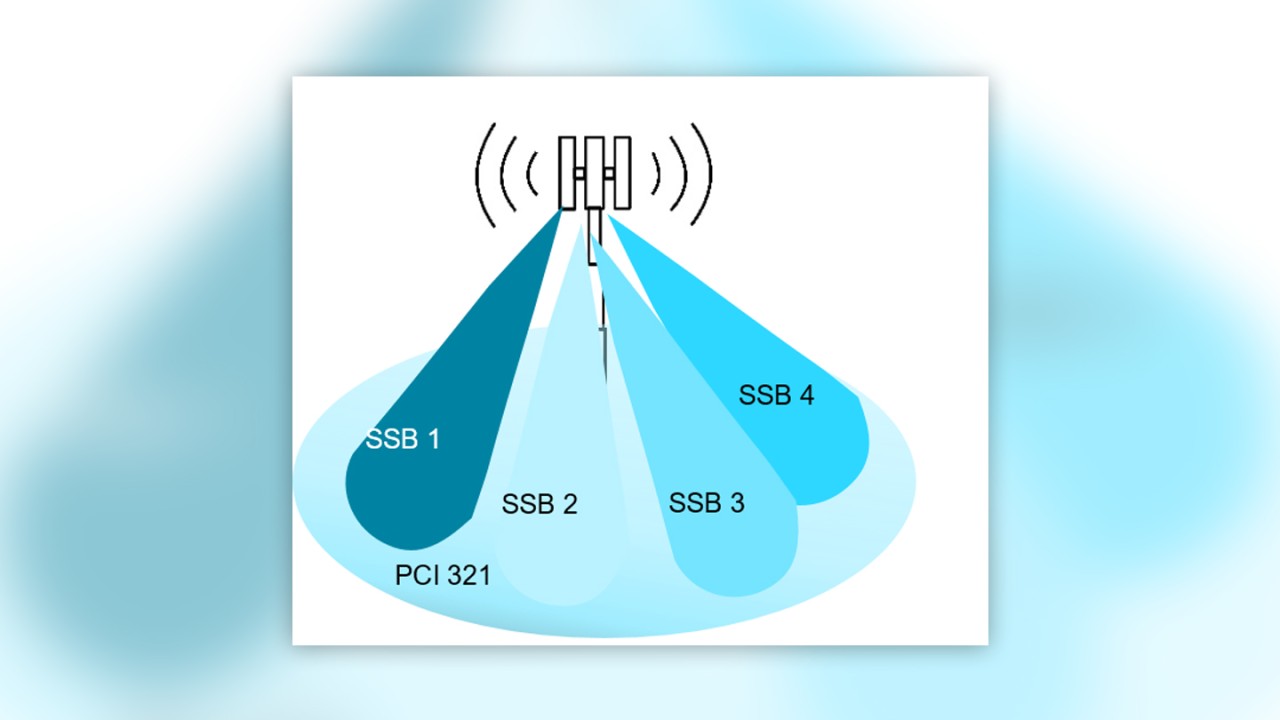
In 5G NR, beamforming is applied to almost all signals, in particular to data channel related signals (PDSCH) and synchronization signal blocks (SSBs).


3GPP defined new bands, such as n77 and n78 (3200 to 4200 MHz), that raised health concerns about increased electromagnetic radiation resulting from higher frequencies combined with beamforming. Consequently, the 5G rollout is slowing down in some countries until it is proven that the maximum radiation is below a certain country-specific threshold.
To prove that country-specific threshold requirements are met, it is necessary to measure electromagnetic radiation or pollution. A perfect measurement method for determining the maximum electromagnetic radiation is the so-called electromagnetic field (EMF) measurements.
Electromagnetic field measurement procedures
There are two fundamentally different EMF measurement procedures, each with several pros and cons: frequency-selective and code-selective measurements. Regardless of the procedure, however, the results of EMF measurements are always as follows:
- Electrical field strength in V/m
- Electrical flux density in W/m²
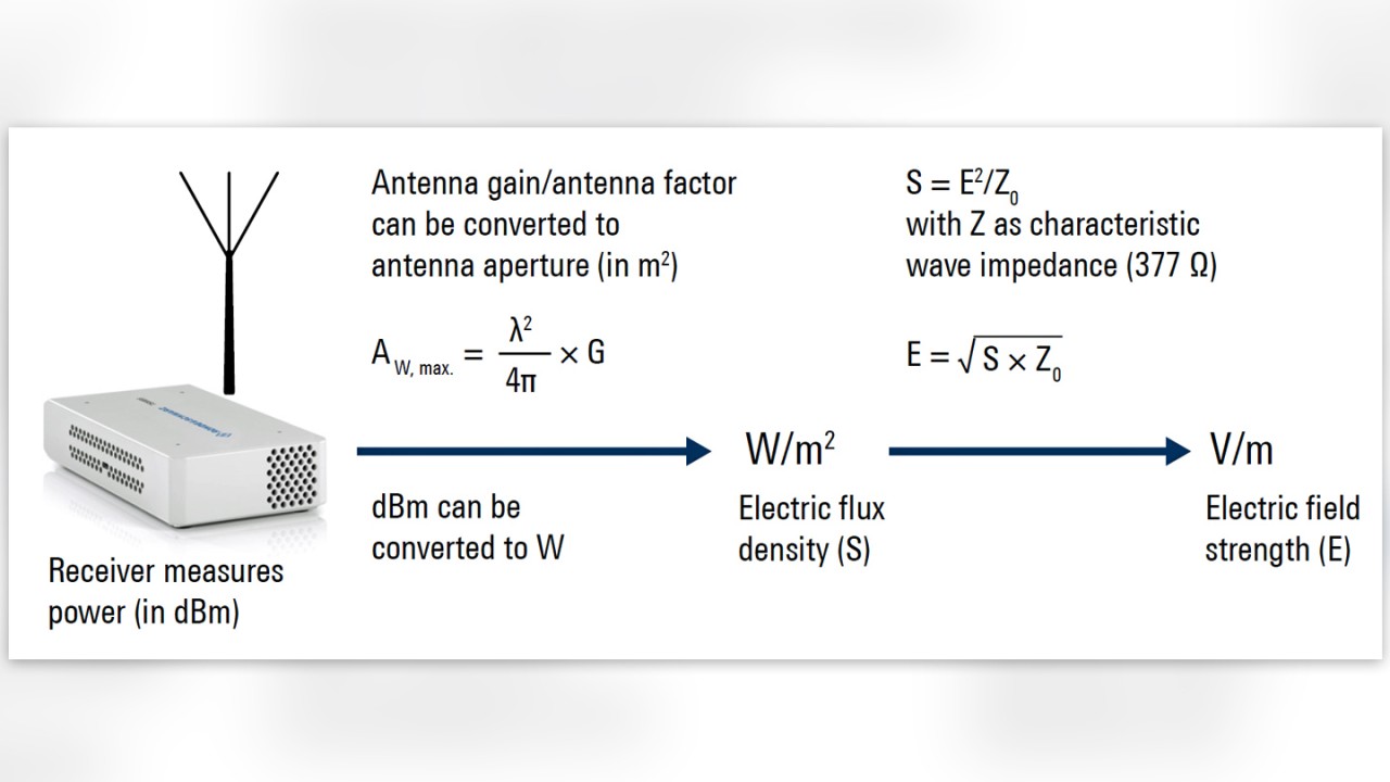
Both measures are based on power measurements (in dBm). By applying the antenna factor (in dB/m) and/or the antenna aperture (in m²), power measurements can be converted into either electric flux density or electric field strength.


Moreover, EMF experts distinguish between current and maximum emission. Current emission measurements refer to a time window of 6 minutes according to the International Commission on Non-Ionizing Radiation Protection (ICNIRP) guideline, while maximum emission measurements focus on the worst-case scenario (maximum traffic).
Which procedure is applied depends on country-specific regulations; in most cases, these are defined by federal institutes or similar organizations.
Frequency-selective EMF measurements
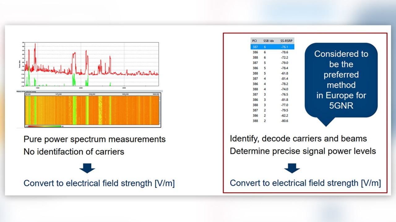
Frequency-selective measurement procedures are based exclusively on power spectrum measurements. Unlike the code-selective procedure, the received signals are neither decoded nor assigned to any technology, operator, or cell; and the signal-specific power and interference are taken into account.


The frequency-selective procedure is the closest in terms of determining the total received power at a certain location. Also, this measurement procedure is likely more useful for current emission measurements. Nevertheless, some practical arguments make the method less attractive than code-selective measurements that are used for determining the maximum emission.
Let’s look at some arguments against frequency-selective EMF measurements in detail, including the antenna and receiver:
- Antenna: The power spectrum of wideband carriers typically changes extremely quickly over time. It is possible to work with envelopes on the power spectrum, but using an isotropic antenna (as required in some countries) is tricky. The isotropic antenna can capture the power omnidirectionally and from all polarizations. It can be controlled, e.g., by a PC, which sends the commands to change the measured polarization at precisely the right time. The isotropic antenna has a certain hysteresis for changing the polarization. During this time, the power spectrum can easily change by 5 or 10 dB depending on cell load and other factors.
- Receiver: Another reason concerns the measurement receivers themselves. Most of them can only capture a spectrum of max. 20 or 40 MHz simultaneously. If more spectrum is requested, they have to retune the front-end and repeat the power spectrum measurement while the power spectrum is continuously changing due to traffic, fading, etc. Hence, the power spectrum is never captured simultaneously, and no unique maximum of the received power spectrum can be found.
Code-selective EMF measurements
What is different when performing code-selective EMF measurements? And, how do the antenna and receiver support arguments for this measurement procedure?
- Antenna: When performing a code-selective measurement, the antenna is typically pivoted to determine the maximum of received power within a certain area or room.
- Receivers: Code-selective measurement receivers can typically detect the center frequency of the carrier automatically, and they are measuring on defined signals and can distinguish between the signal itself and noise.
These receivers deliver a single measurement value (e.g., SS-RSRP) either per PCI or SSB, which is more constant and much easier to handle when searching for the maximum. It is also possible to see the carriers, PCIs, and SSBs that contribute to the total received power/field strength.
As EMF measurement procedures are currently under discussion in several countries, it is still unclear which of the two procedures will prevail and in which countries. One conclusion from the arguments above could be that the code-selective measurement procedure might become the predominant one for maximum emission measurements.
In part 2 of this series about EMF measurements, we will discuss the code-selective measurement procedure in more detail and examine measurement results obtained with our EMF solution comprising the R&S®TSMA6 scanner and QualiPoc Android software.


