Written by Adrian Maurer | August 17, 2021


These buildings are often modern, with windows made of low-emissivity glass that reflect and absorb infrared and heat energy efficiently to improve indoor thermal control. Unfortunately, these types of windows are also very efficient at attenuating radio waves, causing degraded cell phone reception. This degradation affects all kinds of radio technologies and becomes more severe with increasing frequency. With LTE up to a frequency of 2.6 GHz and 5G up to around 4 GHz (not to mention mmWave frequency bands), the attenuation through this type of glass as well as other material is significant. To meet the needs of indoor communications via outdoor base stations, operators have to deal with an attenuation range of 20 dB to 30 dB, and even higher for higher frequencies.
Additional indoor base stations, such as small cells, address this issue and optimally benefit operators and users alike. But only if their installation is close to where additional capacity is required (i.e. close to people) and an SINR can be achieved that is comparable to the existing (macro cell) deployment. A high SINR results in high additional capacity created by the new base station. In conclusion, capacity expansion should ideally be implemented for indoor deployments.
This document deals with the entire indoor deployment cycle of mobile networks, such as distributed antenna systems (DAS) and small cells. It highlights the characteristics of these systems, the planning phase, installation and verification of the deployed system. And finally, it describes mobile network testing solutions to verify successful mobile network deployments indoors.
For indoor deployments, we generally distinguish between two models:
- Distributed antenna systems (DAS) of various types such as passive, active and hybrid
- Small cells, e.g. femto, pico and microcells


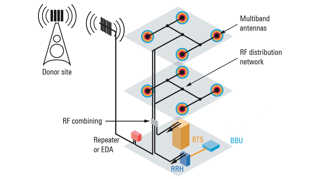
A passive DAS is a simple coverage solution for smaller buildings. It is difficult to modify because of the long length of semi-rigid coax cables used and the limited ways in which to adjust power at each antenna, which is necessary to ensure good coverage. Whatever is done to adjust power at one antenna will affect other power levels at other antennas.
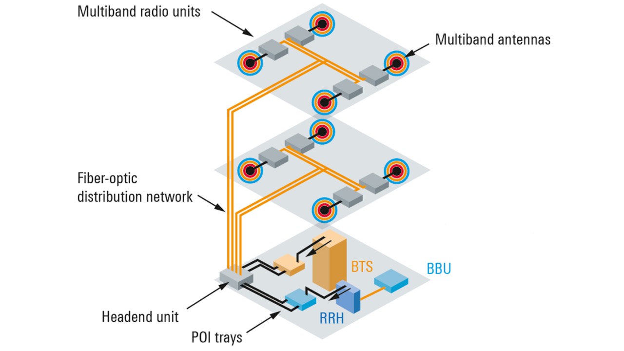
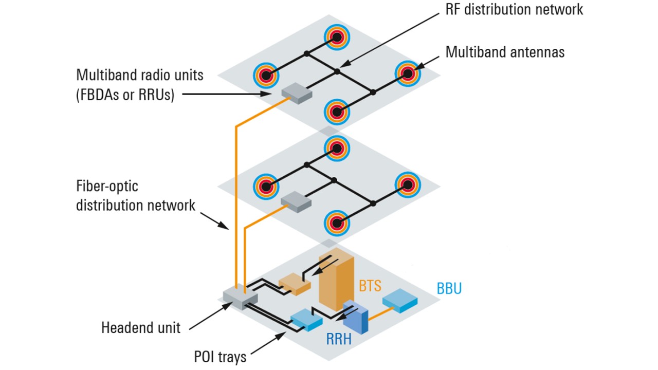
Active DAS systems offer the greatest installation flexibility, since fiber is much easier to install and route than RF cable, and it is much easier to adjust capacity and power levels at each antenna for good coverage. They also provide a high level of flexibility in the selection of RF signal sources when adjusting cellular sectors.
A hybrid DAS combines the benefits of both the active and the passive DAS.
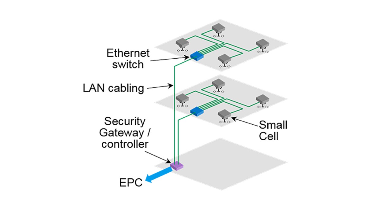
Small cells are small base stations with lower transmit power levels. The umbrella term “small cells” encompasses all kinds of base stations that are smaller than macro cells. Small cells offer very high RF performance and huge flexibility. A small cell deployment is often more cost-efficient than a DAS system.
Steps for efficient implementation of indoor deployments
Typically, indoor deployments comprise three phases:
1. Network planning and design (planning)
2. Installation and commissioning (installation)
3. Site acceptance (verification)
Planning phase
Successful and cost-effective planning of small cell deployments requires planning tools that ensure maximum reliability and accuracy. This, however, is not always the case as floor plans might be outdated and change records of live deployments not properly updated.
Well before the site survey takes place, an indoor deployment must be designed in a back office using planning tools to capture and centralize customer requirements. For example, with the help of the industry’s leading indoor planning software supplier iBwave which uses a file format supported by Rohde & Schwarz measurement solutions.
Installation phase
Following successful execution of the network planning and network design phase, the most critical phase of small cell deployment now begins: the actual indoor installation and commissioning. Many subscriber issues originate in the antenna system. Reasons for that could be reflections in the antenna system caused by damaged cables, or poor positioning of antennas, which results in a poor coverage due to zone overlapping.
Many of these errors can be avoided, if the installation is done correctly.
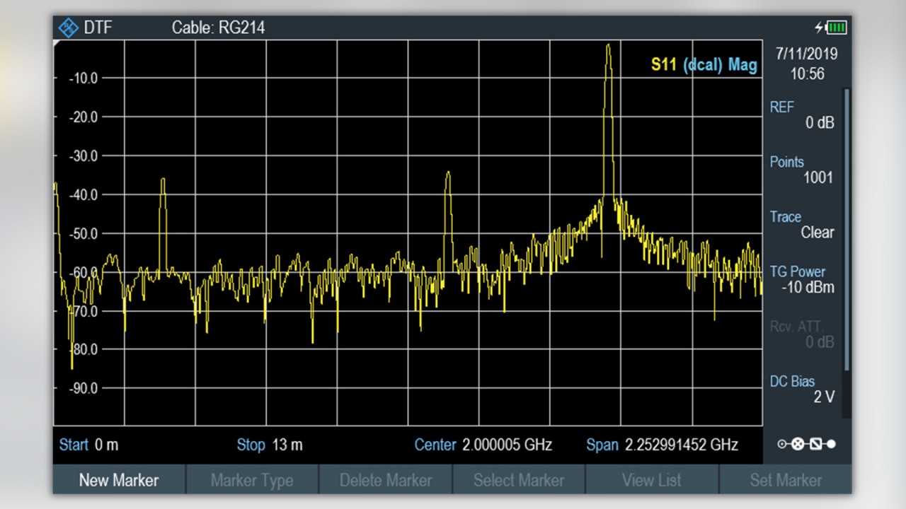
In passive and hybrid DAS, for example, technicians should always test the RF cable and antenna to avoid installing damaged goods. In the screenshot below, you can see a distance-to-fault measurement which is an example of an action that could prevent errors before installing.

Verification phase
After the careful planning and actual installation of a new indoor network, it is time to verify the commissioned indoor deployments and ensure quality of experience (QoE) for the end users. Both are best achieved using a commercially available smartphone that is designed for reliable indoor deployment verification and also features dedicated testing functionalities for final site acceptance.

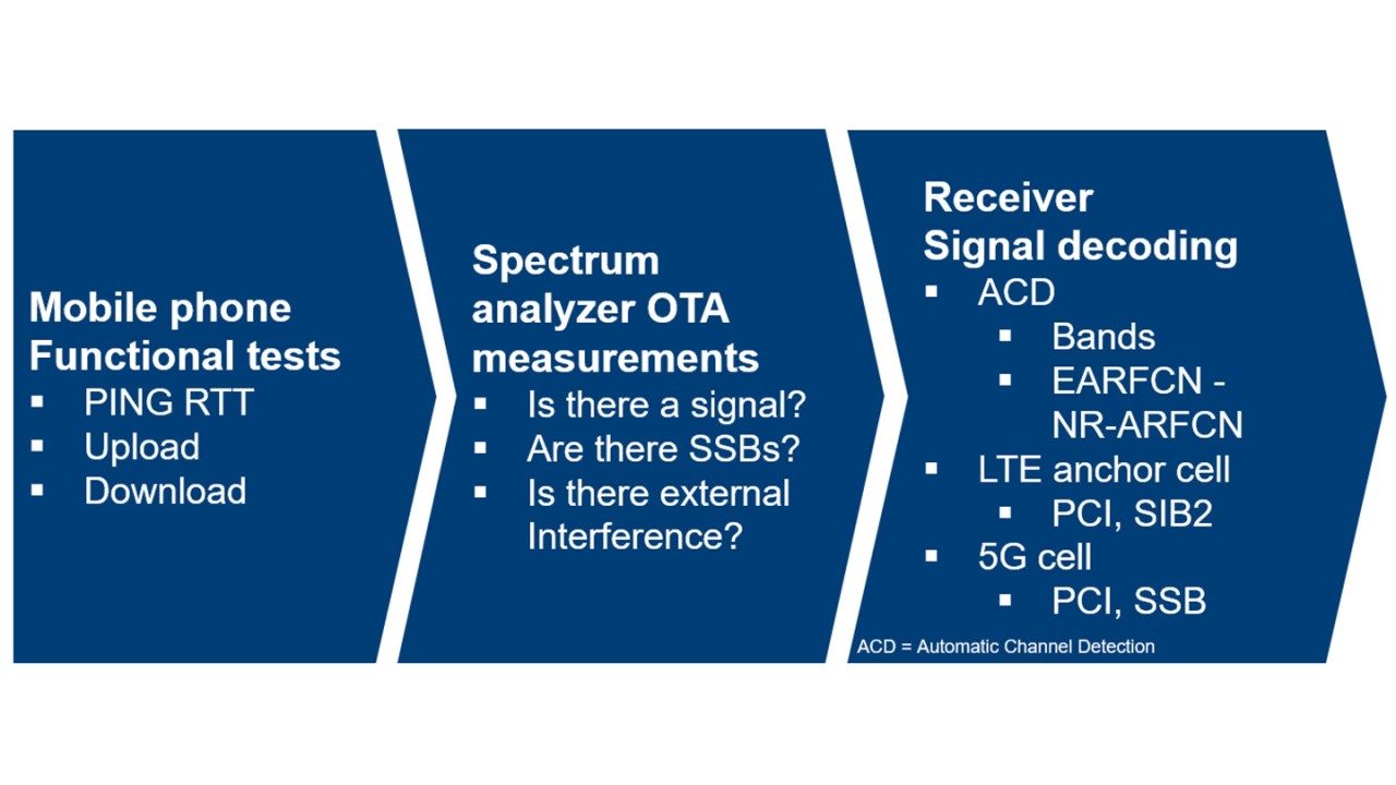
These are the three phases of a complete site acceptance procedure. The procedure begins with mobile phone functional tests. In case of issues, OTA measurements need to be executed for further investigation. If the performance is not optimal or doubts still exist, troubleshooting with measurement equipment that is able to decode received signals is required.
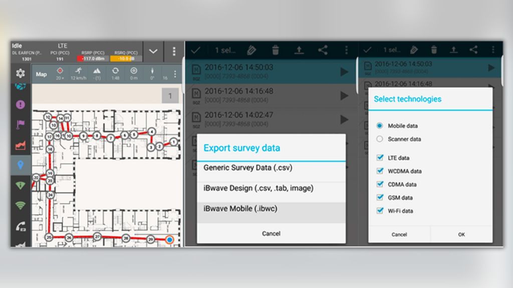
The best and easiest way to perform the functional test is by using a smartphone. Ideally, the smartphone and in particular the prepared software on the smartphone should support the project file format of the specialized planning, mapping and design software to ensure that data such as collected measurement results can be exchanged quickly.
If any of the previous measurements have a different outcome than expected, the next step is to take measurements using a spectrum analyzer. First of all, we need to verify that the signal (e.g. 5G signal) is really transmitted by the base station. Now we need to check whether all synchronization signal blocks (SSB) are receivable. The question remains whether any external interferences impact the network performance.
Therefore, we need to examine the uplink for interference. In TDD networks, the downlink covers the uplink (on the same frequency) for most of the time so that it is very difficult to identify interference in the uplink direction, which is the weaker link, and the uplink interference affects the whole cell. Separating the uplink from downlink with a gated trigger will reveal interference, if there is any.

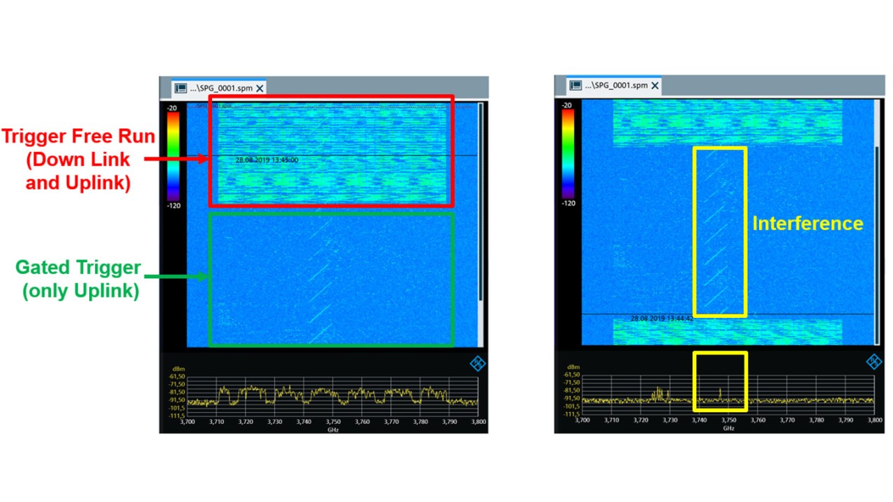
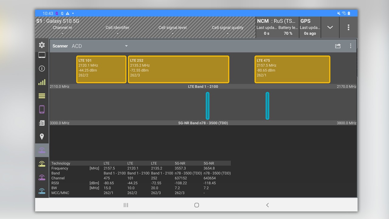
After the uplink, we examine the downlink details. An automatic view showing all available signals on the air interface including e.g. the accurate SSB frequency in 5G in the specific bands is beneficial for identification.
Bear in mind that the SSB and its precise frequency are often difficult to find in running networks.

Passive / active DAS and small cells all have different pros and cons and operators / landlords must select the most suitable solution on a case-by-case basis. No matter what in building solution is chosen, the installation cycle has to be supported with network tests to achieve a high network quality and performance.
Rohde & Schwarz offers a full range of network test solutions for all cellular technologies including 5G to support the different phases of the whole process.
For further information about our solutions please visit our installation and maintenance webpage.


