Background
A perfect electrical supply would deliver a constant frequency sinusoidal voltage waveform with unvarying magnitude. In daily work, power supplies deviate from this ideal situation because system loads vary and phenomena such as transients and outages may occur. If the power quality of the network is good, loads connected to it will run satisfactorily and efficiently. Insufficient power quality, however, can lead to failures of machinery, electric control systems or computers connected to the electrical supply network.
Power quality measurements characterize the degree to which a practical supply resembles the ideal situation, in terms of harmonic pollution, reactive power and load imbalance.
This entails measurements on the supply including frequency, interruptions, flickering, harmonic and interharmonic voltage, voltage variations like dips, temporary overvoltage or rapid changes and voltage unbalance. The EN 50160 standard defines the supply voltage characteristics of the electricity by public distribution systems for these measurements. The standard also includes compliance limits (see table).
How to measure power quality
The R&S®Scope Rider RTH handheld digital oscilloscope integrates eight test instruments in one rugged, batteryoperated device, which makes it a perfect solution for this application. Four isolated input channels with CAT IV 600 V rating allow for measurements on three-phase systems without compromising on safety and without the need for expensive high-voltage differential probes. The long-term logging capability as well as the history functionality allows to monitor and capture slowly varying signal changes or rare events as required by the EN 50160 standard. A capacitive touch screen allows to adjust settings easily while dedicated keys provide quick access to important functions. For measurements in high-risk areas the integrated WLAN interface enables remote operation from a tablet computer or even a smart phone.
Harmonics and power factor
With the R&S®RTH-K34 harmonics analysis option, harmonics up to the 64th order are easily measured and the total harmonic distortion (THDr and THDf) is determined.
When pressing AUTOSET the oscilloscope automatically detects the fundamental frequency within a range of 10 Hz and 1 kHz which makes it possible to measure also specialized electrical networks like in airplanes. The instantaneous magnitude, phase and frequency values of each harmonic component can be displayed as well as the maximum value since start. Results can be compared with EN 50160 or user defined limits.
| EN 50160 compliance limits | ||
|---|---|---|
|
Supply voltage characteristic |
Statistical evaluation | Compliance limit |
| Power frequency |
95 % of the time in one week |
50 Hz ± 1 % |
|
100 % of the time in one week |
50 Hz + 4 % to –6 % | |
| Supply voltage variations |
95 % of the time in one week |
Vc ± 10 % |
| Supply voltage dips | 1 year | none given (indicative value of 1000 dips/year provided) |
| Short interruptions | 1 year | none given (ndicative value of several hundreds of short interruptions/year provided) |
| Long interruptions | 1 year | none given (indicative value of 50 long interruptions/year provided) |
| Temporary overvoltages | 1 year | none given |
|
Supply voltage unbalance |
95 % of the time in one week |
< 2 % |
| Harmonic voltage |
95 % of the time in one week |
THD < 8 % |
| Mains signalling voltage |
99 % of the time in one day |
9 % at 100 Hz, 1 % at 100 kHz |
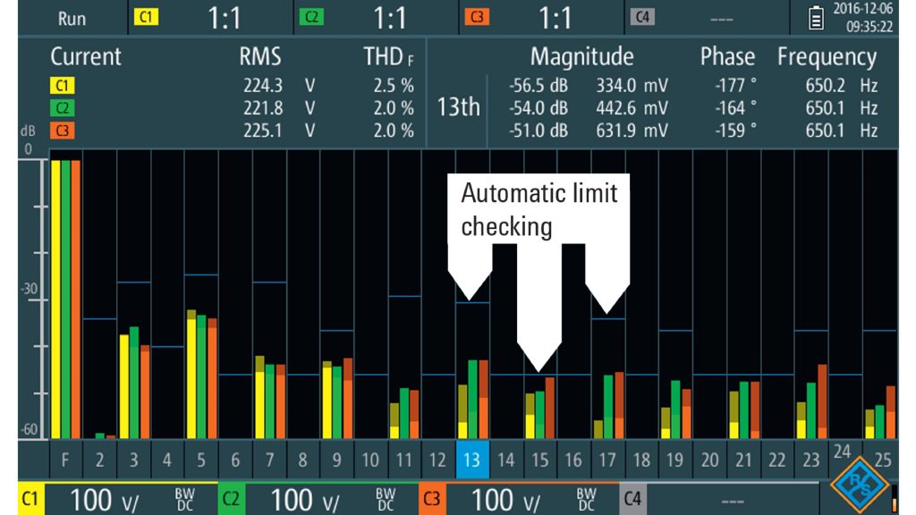
Harmonic analysis of a three-phase system with automatic limit checking.
Identifying the source of unwanted harmonics does require to measure the power factor of individual loads. Automatic oscilloscope measurement functions include active and reactive power as well as the direct measurement of the power factor.
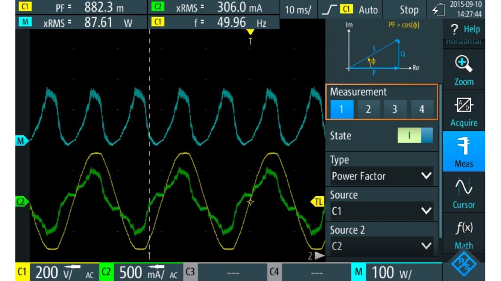
Power factor measurement of an electronic load with automatic measurement functions.
Voltage outages, glitches or variations
Voltage outages and glitches are easily detected with the width trigger. It compares the measured pulse width with a defined time limit to detect pulses which are shorter or longer than a given time interval. Combined with the R&S®RTH-K15 history and segmented memory option, users can capture and collect unwanted events over a long time period and analyze them later. With the time stamp saved automatically for each acquisitions, users can easily correlate electrical network faults with other events in the electrical distribution network to identify problem sources.
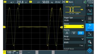
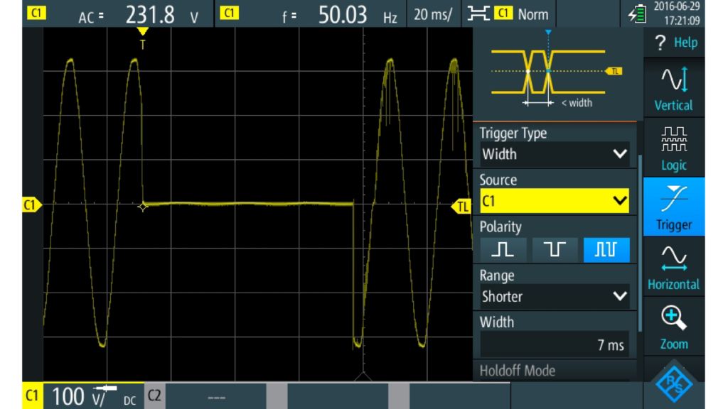
Dedicated trigger functions, for example the width trigger, allow to isolate unwanted events like supply voltage dips.
Voltage variations are efficiently monitored using the logger mode. Based on any set of up to four automatic oscilloscope measurements, results are automatically logged for up to 23 days. Hourly, daily or weekly variations in the voltage, frequency or any other relevant measurement can easily be uncovered.
Summary
Verifying power quality and troubleshooting problems in electrical installations requires to perform a number of quite different measurements. Providing eight test instruments in one rugged, battery-operated device, the R&S®RTH handheld digital oscilloscope is a flexible and powerful solution for this application. Built-in functions include automatic power factor and voltage measurements as well as logging to characterize intermittent and long-term voltage variations. Voltage dips can be recorded using extended trigger capabilities like the pulse width in combination with the R&S®RTH-K15 history option. The R&S®RTH-K34 software option allows for an automated harmonic analysis. Voltage variations are efficiently monitored using the logger mode. Based on any set of up to four automatic oscilloscope measurements, results are automatically logged for up to 23 days. Hourly, daily or weekly variations in the voltage, frequency or any other relevant measurement can easily be uncovered.


