Oscilloscope probe tips and how to use them

Interested?

R&S®ESSENTIALS | Digital oscilloscope and probe fundamentals

How to use your oscilloscope probe: oscilloscope probe tips

Author: Paul Denisowski, Product Management Engineer

Get the most out of your oscilloscope with our basic guide to best practices for oscilloscope probing. We’re going go over eight important tips to ensure accurate reliable measurements. From compensating passive probes to degaussing current probes - we've got you covered.

Oscilloscope probe types

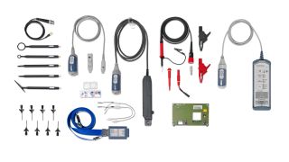
There are two main types of oscilloscope probes: active and passive. The choice between the two boils down to a trade-off between simplicity and sophistication.

Passive probes are more straightforward - they require no external power source and are cost-effective. They are reliable, rugged and very easy to use: connect to the scope, attach the ground lead, and you’re ready to go. A set of passive probes often comes bundled with oscilloscopes, making them readily available for a variety of basic measurements.

Active probes, on the other hand, bring a higher level of precision and performance to the table - or rather, the bench. As their name suggests, these probes are equipped with active components that allow them to handle high-frequency signals. This also means that they come with a higher price tag, but their greater flexibility and enhanced sensitivity make them indispensable for applications that demand high accuracy.

Ultimately, the choice between passive and active probes depends on the specific requirements of the task at hand. It's a matter of balancing the demands of the measurement with your budget and desired level of performance.

Passive probe

Active probe

Compensating passive oscilloscope probes

Passive probe compensation is crucial for ensuring the accuracy and reliability of oscilloscope measurements. When an oscilloscope is connected to a passive probe without proper compensation, this can lead to distorted and inaccurate waveform representations. This distortion becomes particularly pronounced at higher frequencies, impacting the fidelity of the measured signals. By fine-tuning the probe's capacitance through compensation, the goal is to achieve a flat and accurate frequency response, especially across the entire bandwidth of the oscilloscope.

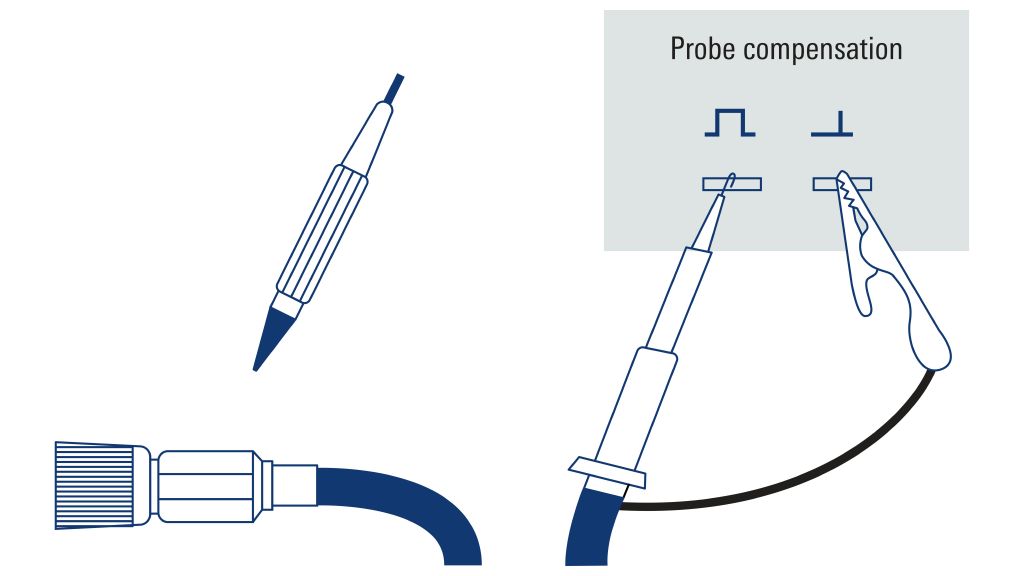
The compensation process involves adjusting the variable capacitance within the passive probe to counterbalance the inherent input capacitance of the oscilloscope. Most oscilloscopes have a built-in 1000 Hz square wave generator for probe compensation.

  • Step 1: Connect the probe tip to the signal source.
  • Step 2: Connect the probe ground lead to ground.
  • Step 3: Configure the oscilloscope to display the probe compensation output.
  • Step 4: Insert a non-conductive tool into the small hole in the probe compensation box.
  • Step 5: Rotate this tool to adjust the probe’s capacitance until the displayed square wave is as rectangular as possible.
 How to compensate a passive probe
How to compensate a passive probe

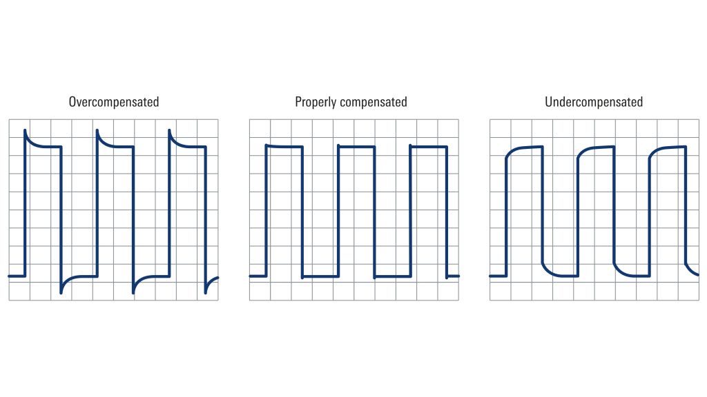
A probe is properly compensated when the tops of the displayed compensation signal are more-or-less horizontal. Overcompensated probes exhibit overshoot on the leading edge of the signal, while undercompensated probes exhibit undershoot on the leading edge. To fix this, the compensation capacitor must be adjusted until the waveform edges are distinctly rectangular. Typically, this fine-tuning requires only a small fraction of a turn.

Displayed compensation signal

Using shortest possible ground leads with passive oscilloscope probes

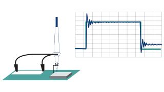
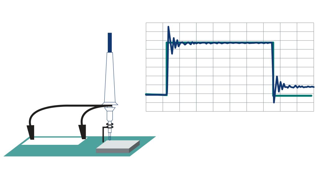
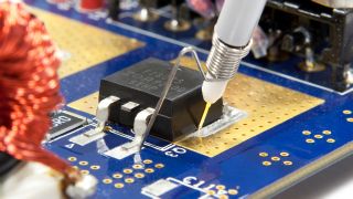
Another important tip when using passive probes is to minimize the length of the ground connection. Passive probes operate in a “single-ended” manner: they measure voltage relative to ground and require a solid ground connection. This connection is typically established through a ground lead with an alligator clip, and it is important to keep this lead as short as possible. Long ground leads introduce inductance to the measured signal, impacting higher frequency components and potentially causing ringing, overshoot or undershoot in square wave signals. Note that when a ground point is available near the measurement point, a slip-on spring style ground lead can further reduce the length of the ground connection.

Inductance caused by long ground lead

Selecting the correct input impedance

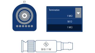
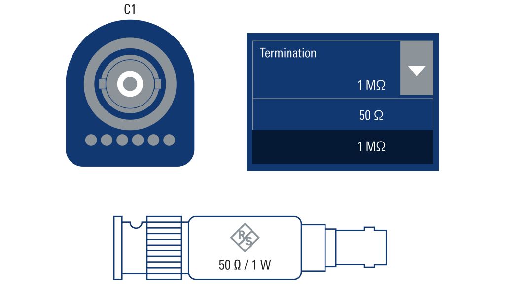
Now, let’s delve into configuring the channel input impedance. With certain oscilloscopes, users have the flexibility to choose between a 50 ohm and a 1 megaohm input impedance. The selection of the input impedance to match the impedance of the signal source or the probing setup is called “termination.” This is done on a per-channel basis through the scope interface. The “standard” impedance for an oscilloscope input is typically set at 1 megaohm, which is the appropriate choice when working with passive probes.

However, when active probes or a direct connect using a BNC cable become involved, the optional 50 ohm termination becomes relevant. Many test and measurement instruments, as well as RF devices, utilize 50 ohms as their standard termination. Selecting the correct input impedance is crucial because an incorrect setting can impact the measured signal amplitude. For instance, setting the termination to 1 megaohm instead of 50 ohms might result in observing double the expected voltage.

As a final note, it is good to keep in mind that the maximum safe input voltage can differ significantly between the two terminations. Setting the termination to 50 ohms, as opposed to 1 megaohm, often imposes a lower threshold for the maximum safe input voltage. Some oscilloscopes may lack native support for a 50 ohm termination, but in such instances, specialized feedthrough adapters can be employed to provide the required 50 ohm termination when necessary.

Some oscilloscopes have a selectable channel input impedance

Degaussing and zeroing current probes

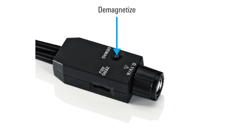
Let’s shift our attention to current probes: it’s important to know that a current probe’s ferromagnetic probe has the potential to retain magnetism or “flux” even in the absence of current. This is a common phenomenon and happens frequently after a probe has been used to measure a current that was switched on and off. The lingering magnetism can introduce an offset and influence measurement accuracy. To address this, most current probes are equipped with a demagnetizing or “degauss” function, which can be activated either directly on the probe or through the oscilloscope’s user interface.

When initiated, the degauss function generates a specialized waveform, creating an essentially random magnetic field that “erases” any residual magnetism in the probe. This is typically a very quick process that takes only a few seconds. Therefore, it is a good idea to degauss a current probe both before zeroing and before conducting measurements.

Degaussing is a button press away

Using multiple windings for better sensitivity

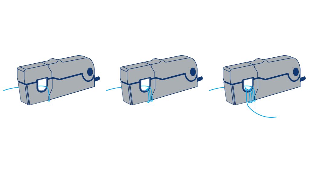
Here’s another tip for using current probes: you can loop the conductor through the probe multiple times to improve measurement sensitivity. The sensitivity of the probe increases linearly with the number of loops. For example, looping the conductor four times increases the sensitivity by a factor of four. Since an oscilloscope can’t automatically determine the number of loops, you must manually input the appropriate scaling value.

These loops increase the insertion impedance significantly - by the square of the number of loops - but the impact on measurements at low current levels is negligible. The increase insertion impedance remains relatively small and does not substantially affect measurement accuracy.

Wind the conductor through the probe to improve sensitivity

Deskewing probes for power measurements

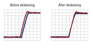
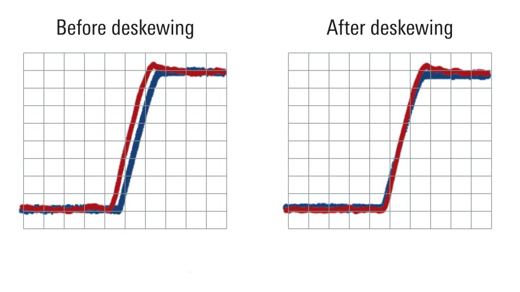
For power measurements, current probes are often used with voltage probes. This is because accurate power assessments require measuring both voltage and current. However, discrepancies in propagation times through probe leads may introduce a time offset or “skew” between the measured voltage and current waveforms, potentially leading to inaccurate power readings.

The solution is specialized deskew fixtures, which detect and compensate for the skew by generating time-aligned voltage and current pulses. These synchronized pulses are concurrently measured by connected current and voltage probes. If the test waveforms exhibit any skew, an appropriate deskew or time offset value can be input into the oscilloscope. This correction brings the current and voltage waveforms back into alignment, improving measurement accuracy.

Before and after deskewing

Using differential probes to make floating measurements

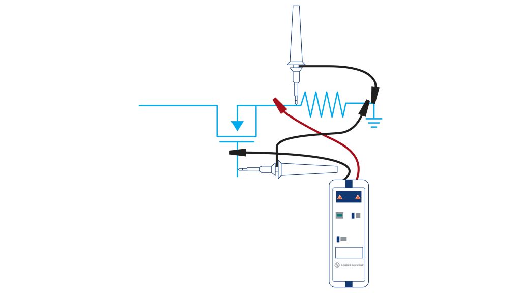
Oscilloscope probes normally measure voltage with reference to ground; this is called a “single-ended measurement.” However, “differential measurements” become necessary if you need to measure the voltage across components that are not connected to ground. Such measurements are sometimes called “floating measurements.”

One way of conducting a differential measurement involves using two single-ended probes, measuring with respect to ground at two points, and then subtracting these voltages within the scope. This is called a “quasi-differential” measurement.

A more effective approach is using a dedicated differential probe equipped with an internal differential amplifier. This probe produces a voltage corresponding to the difference between the voltages at the two connection points. Differential probes excel in floating measurements for several reasons:

  • They can measure voltage between any two points.
  • They offer higher accuracy by rejecting common mode noise, i.e., noise that is common to both inputs.
  • They play a crucial role in safeguarding devices and operators from high currents resulting from accidental or inadvertent ground connections.
Using a differential probe

Using active probes for challenging measurements

Our final tip: use an active probe for more demanding measurements. As mentioned earlier, active probes have powered components, typically a field-effect transistor (FET) in the probe tip. The design of active probes results in significantly lower input capacitance compared to passive probes. This reduced capacitance offers two notable advantages:

  • It minimizes circuit loading, enabling a more faithful reproduction of the measured signal on the oscilloscope and a lower impact on circuit operation.
  • It provides a higher bandwidth, crucial for accurately measuring high-speed signals, especially those with prominent high-frequency components like square or pulsed waves.

In addition, certain active probes can apply a substantial offset to the signal. This feature is invaluable when measuring small AC signals superimposed on larger DC signals, such as power supply ripple.

Summary

  • It is necessary to compensate passive probes to ensure the accuracy and reliability of oscilloscope measurements
  • With passive probes, you should use the shortest possible ground leads
  • Make sure you select the correct input impedance
  • It is a good idea to degauss a current probe both before zeroing and before conducting measurements
  • You can loop the conductor through a current probe to improve measurement sensitivity
  • Use deskew fixtures to detect and compensate for skew by generating time-aligned voltage and current pulses
  • Try using a dedicated differential probe for floating measurements
  • Use active probes for more demanding applications

Do you want to know more?

Curious to learn more about test fundamentals?

Sign up for our newsletter