Simulate many radar emitters for receiver tests

The R&S®Pulse Sequencer software together with the R&S®SMW200A vector signal generator offers a simple and easy way to simulate multi-emitter environments. It enables engineers to validate and verify the EW receiver performance.

Your task

Radar warning receivers are a core part of early warning (EW) equipment. The main task of this equipment is to protect and warn pilots in aircraft or to protect assets such as aircraft or installations. The purpose of the equipment is to quickly detect, identify and classify radar signals. For this purpose, it compares the received signals against an installed library that holds parameters of known emitters such as modulation on pulse (MOP), pulse duration, carrier frequency and pulse patterns. In operational situations, there are usually a lot of signals present that need to be processed in a very short time. Knowledge of the nature of a received radar signal is essential in operational and dangerous situations. For productive and efficient engineering of EW receivers, it is vital to ensure a realistic and representative test environment with multiple emitters in the lab to prove that an EW receiver can detect a wanted signal that is hidden in a dense multisignal environment.

Example of a scenario with six emitters
No. Frequency in MHz PRI in μs Intra/interpulse modulation PW in ns
1 3042 ± 40 1755 9-element RF stagger 353
2 3300 569 to 608 4-element PW stagger 222 to 252
3 3150 973 to 1097 32-element PRI stagger 400
4 2950 387 to 411 3-element PW stagger 440/450/460
5 3200/3240 630
2-element RF on / off:
15 ms/5 ms
305
6 2900 577 to 677 random PRI 500

T&M solution

In order to simulate multi-emitter scenarios, engineers use the R&S®SMW200A vector signal generator together with the R&S®Pulse Sequencer software. With the R&S®SMW-K306 multiple emitters option installed, the R&S®SMW200A turns into a powerful and modern radar signal simulator for EW receiver tests. Engineers now have a handy tool and a perfect alternative to large simulators for the complete development cycle of EW receivers. It prevents delays, design rework and perfectly balances cost with performance. Radar engineers can use the R&S®Pulse Sequencer software to create lists of radar emitters (see table). The R&S®Pulse Sequencer software simulates multiple emitter signals and combines them into a single output file, using an optimized, priority-based and smart interleaving algorithm. The benefits are:

  • Simple, customized configuration of up to 256 emitters
  • Optimize and preview interleaving results thanks to priority schemes and offset parameters
  • Interleave emitters that use I/Q modulated pulses or inter-pulse modulation profiles such as PRI stagger, RF stagger and any kind of antenna scan type or antenna patterns
  • Interleave emitters that switch modes over time
  • Import and interleave PDW lists

Create emitters with interpulse modulation and MOP

Radars have characteristic signatures, such as staggered or randomly varying pulse repetition intervals (PRI) or staggered RF frequencies (frequency hopping). Pulses can have modulation MOP, e.g. with linear frequency modulation. Especially low probability of intercept (LPI) radars use MOP and benefit from pulse compression gain in order to decrease the radiated power per pulse. The more complex, agile and advanced emitter signatures are, the more difficult it becomes for EW receivers to detect them among a mix of many other emitters. The R&S®Pulse Sequencer software can simulate all the characteristics listed above for multi-emitter scenarios. In the example test case used here, the scenario consists of six different (1 to 6) radars listed in the table. In this test case, the EW receiver has to detect the land-based early warning radar (radar 6) installed near the coastline within the mix of active commercial navigation radars (radars 1 to 5).

Can your EW receiver detect the wanted radar emitter
Can your EW receiver detect the wanted radar emitter?

Interleave emitter signals based on user priorities

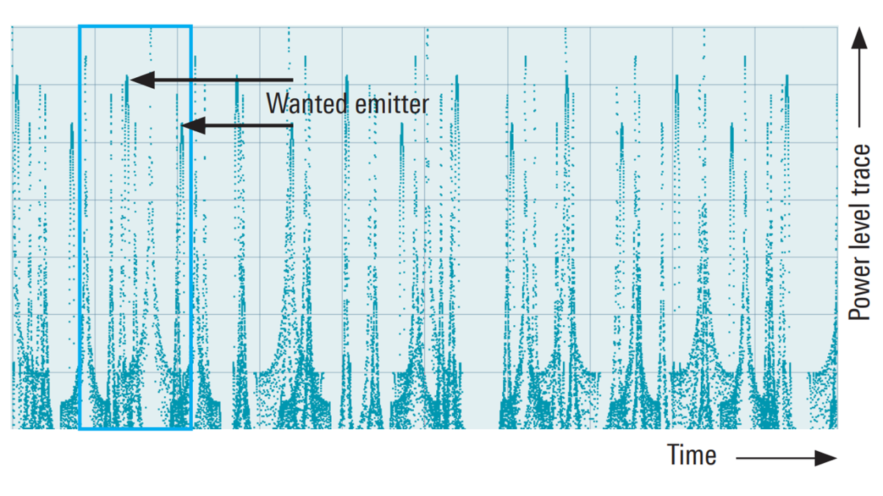
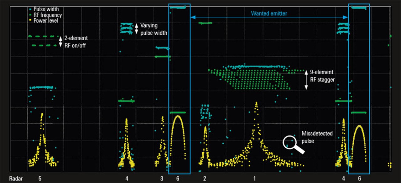
Engineers want to minimize the number of RF sources and maximize the number of produced radar signals. A good approach is to interleave the individual radar signals and produce a single combined signal. Due to the high density of radars present, it is likely that pulses overlap and create pulse-on-pulse situations. The R&S®Pulse Sequencer software uses an algorithm to interleave signals and drop pulses in case they collide – based on an optimized, userdefined priority scheme. This ensures lowest drop rates. As an example, the mentioned radar emitters have been interleaved by the R&S®Pulse Sequencer software and the resulting multi-emitter signal has been generated. The figure above shows the simulated power level traces and the variation of the six simulated and interleaved radar signals over time. In order to demonstrate the complexity of the EW receiver’s job, a measurement of the indicated time interval (blue frame) of the level trace is displayed in the screenshot below.

The receiver has to identify radar emitter 6. However, it also sees all the other radars. The EW computer now needs to process the following radar emitter signals: Radar 1 varies its RF frequency within nine values with 10 MHz step size, leading to frequency steps (green dots) in the figure below. Radar 4 varies its pulse width between three values (three blue bars). Radar 5 turns its RF on and off, switching between two different RF frequencies (green dashes). In the blue frames, the emitter of interest (radar 6) is highlighted. This emitter has peaks with different levels in its power level trace due to its antenna scan. The RF frequency of 2900 MHz (green bar) and PW of 500 ns (blue bar) are constant over time. The EW computer has also to cope with the effect that outside of the main lobes, some pulses are detected with an incorrect pulse width and frequency. This can be due to a large receiver bandwidth and the receiver’s subsequent reduced signal-to-noise ratio (SNR).

Key benefits

  • Validate and verify your EW receiver performance in a dense, multi-emitter environment with an R&S®SMW200A
  • Turn the R&S®SMW200A together with the R&S®Pulse Sequencer software into a powerful radar signal simulator
Measurement of a multi-emitter scenario with highly agile radar signals
Open Lightbox