Speeding up reflection measurements on antenna systems

Reflection measurements are a common way of assessing antenna system performance. When a minimum amount of the transmitted signal is reflected, it indicates that the transmission energy can reach the intended coverage. Undesired high reflection causes the system to be inefficient and can damage components. Reflection measurements can be expressed in terms of return loss, VSWR and reflection coefficient.

Your task

Component faults decrease the performance of the entire base station. The signal level is reduced, which affects the cell site coverage area. A mobile phone at cell boundaries will experience dropped calls and low data rates. This will negatively affect the customer experience and will likely result in revenue losses for the network operators. Extreme mismatch scenarios can even damage the transmitter. Performing reflection measurements can determine if all RF energy radiates out as desired.

Return loss and VSWR measurements are the typical reflection measurements performed during installation and maintenance of base stations.

From a practical point of view, the recommended system limit for return loss is more than 15 dB, which means the VSWR is less than 1.43 and the antenna will radiate nearly 97 % of the total energy.

reflection-measurements-antenna-systems_ac_5215-4375-92_01.png

T & M solution

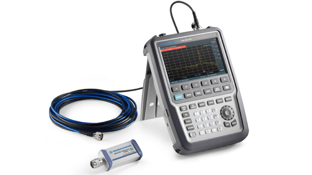
The R&S®Cable Rider ZPH is specifically designed to aid fast and efficient measurements on antenna systems and to get it right first time. The one-port cable and antenna analyzer covers return loss, DTF and other essential measurements for installation and maintenance of radio transmission links in the field.

The fast boot time (< 15 s) and warm-up time (1 min) allow users to start measurements promptly. The wizard function is used to preconfigure the types of measurements and frequency range in the office to prevent incorrect measurements and wrong parameter entries on site. This speeds up the measurements.

Application

At the base station, first calibrate the RF jumper cable with the R&S®ZN-Z103 to eliminate the cable effect. The R&S®ZN-Z103 calibration unit fully calibrates the cable in just 1 minute since it automatically switches between open, short and load standard. Now use the RF jumper cable to connect the flat panel antenna to R&S®Cable Rider ZPH as shown in Fig. 1. The antenna has a specified VSWR of less than 1.3. Based on calculation, the return loss value for this antenna should be better than 17.69 dB.

Under match condition, the measurement result shows a return loss of 18.70 dB (Fig. 2). The corresponding measured VSWR is 1.26 (Fig. 3). This shows that most of the signal is radiated out.

When there is a mismatch due to a faulty antenna or faulty components, transmitted RF energy will be reflected. The amount of reflection depends on the severity of the fault. In the worst case, all transmitted RF energy is reflected back.

Fig. 1: Reflection measurement of a base station antenna with R&S®Cable Rider ZPH.

Return loss and VSWR measurements

Fig. 2: Return loss measured under matched condition, return loss = 18.70 dB.

Fig. 3: VSWR measured under matched condition, VSWR ≈ 1.26.

Fig. 4: Return loss measured with open circuit,return loss = 0 dB.

Fig. 5: VSWR measured with open circuit, VSWR = ∞.

In summary

The R&S®Cable Rider ZPH, a simple one-port cable and antenna analyzer, can be used to swiftly and easily perform reflection measurements and other tasks. Reducing time and errors on site can save operating costs and minimize downtime.

Related solutions