The effective way to measure key mixer performance parameters
Characterizing RF mixers that have an internal LO using the value-of-three R&S®FPC1500 spectrum analyzer.
Characterizing RF mixers that have an internal LO using the value-of-three R&S®FPC1500 spectrum analyzer.
Mixers are frequency-converting components – the input signal has a different frequency than the output signal. A mixer has three connectors: RF (radio frequency), LO (local oscillator) and IF (intermediate frequency). Therefore, mixer characterization typically requires a four-port vector network analyzer. The key test parameters are conversion loss, isolation and reflection. Other parameters include harmonics, 1 dB compression point and intercept points. The relative importance of these individual characteristics varies based on the mixer application.
In the case of a downconversion mixer for a receiver system that operates at lower power level, harmonics and compression point measurements become less significant. In a manufacturing environment, the emphasis is on the cost of testing, so only key parameters are checked during a functionality test.
Some mixers do not require an external LO since they have an internal embedded LO. Such mixers would only have two connectors: RF and IF. These types of RF mixers with embedded LOs are commonly used in the satellite and military industries. Test setups for two-port mixers are simpler.
Fig. 1: Test setup with the R&S®FPC1500
The R&S®FPC1500 can be used to measure the key performance test parameters: conversion loss, isolation and reflection (return loss).

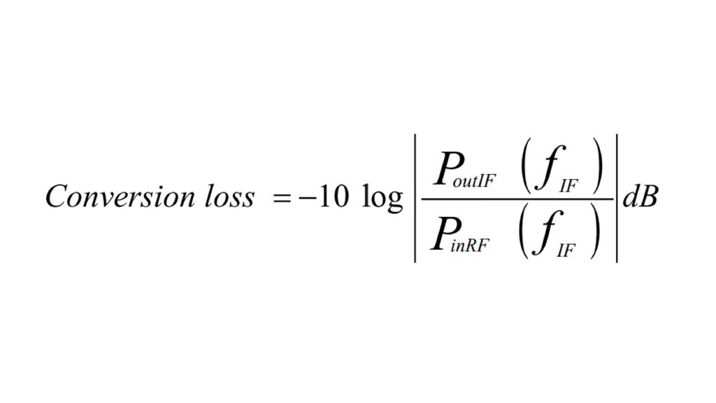
Conversion loss
Conversion loss is a measure of the efficiency of the mixer in converting the frequency from RF to IF. It measures the difference in power between the input RF power level and the output IF power level.
A spectrum analyzer with tracking generator functionality makes scalar transmission measurement possible. The R&S®FPC1500 tracking generator features a frequency conversion option, making it ideal for measurements on mixers.
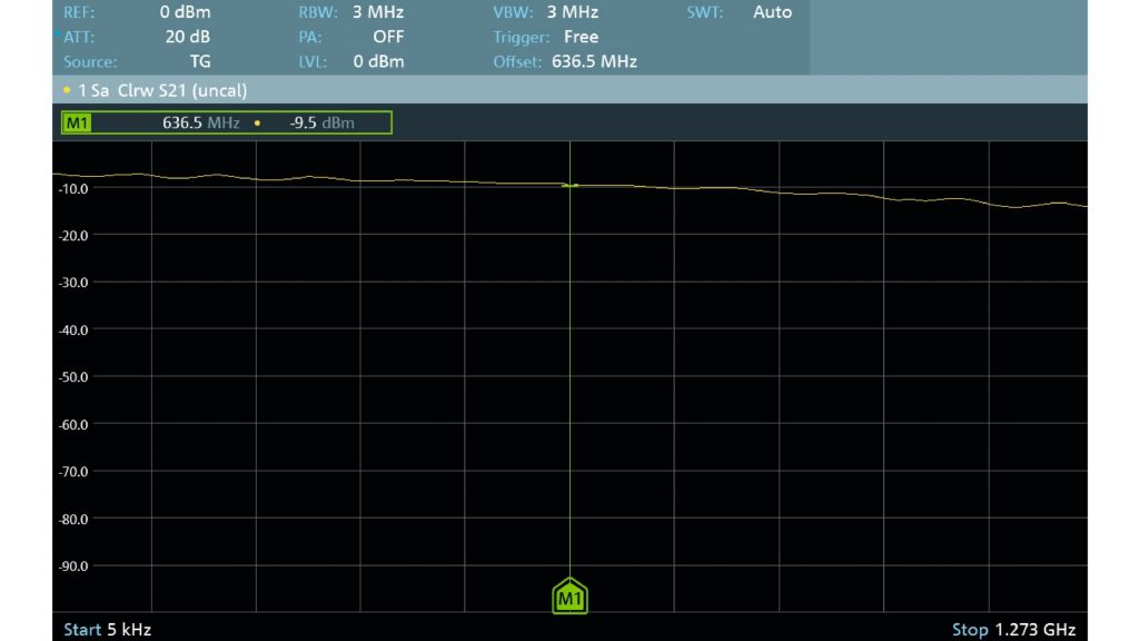
Fig. 2 explains how the measurements are done, while the left screenshot in Fig. 4 illustrates the measurement result from a mixer with a 636.5 MHz internal LO.
Fig. 2: Execution of measurement
The tracking source (RF) starts sweeping from the LO frequency while the analyzer measures the lower sideband of IF (blue).
Fig. 3: Measurement result
Measurement result from a mixer with a 636.5 MHz internal LO
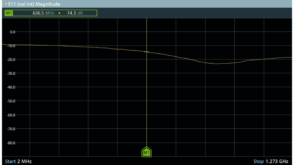
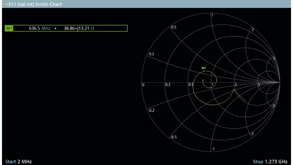
Fig. 4: RF mixer measurement using the R&S®FPC1500
Isolation
Isolation is a measure of signal coupling between the ports of a mixer. RF-IF isolation is the attenuation value between RF and IF. This value shows how much RF input signal is attenuated towards IF. The measurement can be easily accomplished by measuring the IF port with the analyzer set to the RF frequency.
Reflection
Reflection measurements show how good the impedance matching is at an individual port. Traditionally, a vector network analyzer is required for S-parameter measurements like the S11 RF input reflection.
Thanks to the unique design of the R&S®FPC1500 that utilizes an internal VSWR bridge, the spectrum analyzer can perform one-port vector reflection measurements. The middle screenshot in Fig. 4 shows a mixer S11 return loss in dB, the right screenshot in Fig. 4 shows the mixer input impedance in a Smith chart.
Related products