Digital dividend: testing of TV receivers
The R&S®SFU broadcast test system is used as a reference signal generator to simulate the influence of LTE and other mobile radio signals on digital TV signals and receivers.

The R&S®SFU broadcast test system is used as a reference signal generator to simulate the influence of LTE and other mobile radio signals on digital TV signals and receivers.


Testing the influence of LTE signals on TV signal reception
The shutdown of analog TV has freed up TV channels that, as a result of the digital dividend, are now being assigned to mobile radio frequency bands, mostly Long Term Evolution (LTE).
Manufacturers of set-top boxes and TV sets must therefore adapt receiver immunity to the challenges posed by the coexistence of mobile radio and TV signals. Without these modifications, sporadic video and audio disruptions, blocking effects or even a complete picture loss or freeze could occur. Mobile radio signals, however, not only can affect terrestrial receivers but also may radiate into cable receivers and in-building distribution systems.
In the case of terrestrial receivers, LTE signals influence tuners due to insufficient selectivity. Single-carrier methods (e.g. ATSC) are more sensitive than OFDM methods (e.g. DVB-T, DVB-T2). The LTE signals act as adjacent channel interferers.
When housings or coaxial cables are not sufficiently shielded (due partially to defective connections between the shielding jacket and the connector), DVB-C, J.83B or ISDB-C cable receivers are influenced. Co-channel interference may also occur because the entire range from 50 MHz to 1 GHz is completely allocated.
Set-top boxes and TV receivers must therefore be tested using real-world LTE interferers as described in the D-Book of the Digital TV Group (DTG).
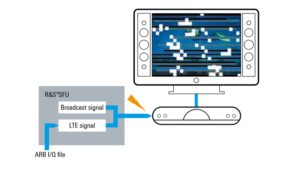
The R&S®SFU broadcast test system is used as the signal source for the wanted TV signal and the LTE interferer. The wanted broadcast signal is generated in the R&S®SFU in realtime for the appropriate terrestrial or cable standard; a transport stream with video and audio content is modulated and transmitted to the receiver. The LTE interferer is also generated in the R&S®SFU by loading an I/Q file (e.g. any LTE I/Q file) into the ARB generator.
Both signals, i.e. the wanted broadcast signal and the LTE interferer, are added in the R&S®SFU and jointly provided at the RF output to be received by the DUT.
For frequency and channel spacings of more than 80 MHz between the wanted and interfering signals, dynamic ranges of more than 60 dB or radiation scenarios, a second signal generator is needed. Higher frequency spacing is of interest particularly with regard to image frequencies that occur with demodulators.
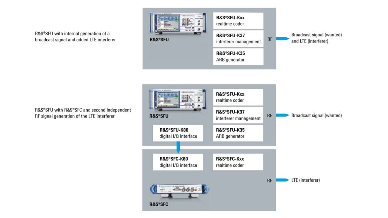
The first test setup is used for simulating terrestrial transmission and requires a terrestrial realtime coder (e.g. DVB-T2, R&S®SFU-K16) for the wanted signal. The interferer is played with the ARB generator. Then either an I/Q file in Rohde & Schwarz format (see application note “7BM79 I/Q waveform file conversion”) or an I/Q file generated with R&S®WinIQSIM2™ with a maximum length of up to 4 Gbyte can be loaded into the ARB generator. If R&S®WinIQSIM2™ generated I/Q waveforms are used, the appropriate option is needed – for LTE, for example, this is the R&S®SFU-K255 option. The LTE interferer and the wanted signal are added using the interferer management option. In this test setup, the wanted and interfering signals are processed in the R&S®SFU and made available at the RF output.
The second test setup uses two coupled signal generators which simulate the LTE influence on cable receivers and distribution systems with a power difference of more than 60 dB. The wanted signal is fed directly into the cable, while the LTE interferer is fed to a second signal generator via the digital I/Q interface. This second signal generator operates as a pure I/Q modulator, i.e. the realtime coder and the ARB generator of the second signal generator are not used. Instead, the signal is fed directly via the digital I/Q input.
The following menus activate the digital I/Q interface on the R&S®SFU for outputting the interferer:
An R&S®SFU, R&S®SFE, R&S®SFE100 or R&S®SFC can be selected as the second signal source.

