Solution for BCI application

For conducted immunity tests, EMC labs require a test signal source driven at high RF powers and at defined frequencies. Rohde&Schwarz offers a compact solution with a signal generator, an RF solid-state amplifier with power up to 350 W, power sensors and test software for the frequency range from 4 kHz to 400 MHz.

Your task

Bulk current injection (BCI) is a conducted immunity test method in line with ISO11452-1 and ISO11452-4. A cur?rent injection probe is used to induce current (disturbance) in the wiring harness of the device under test (DUT). The ISO11452-4 standard specifies two BCI test methods: the substitution method and the closed loop method.

Solution-for-BCI-application_ac_01_1440x.jpg

T&M solution

Rohde&Schwarz offers a robust and compact solution to provide conducted immunity tests, covering both the substitution and the closed loop method.

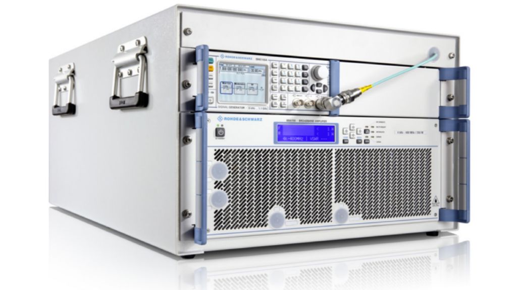
An R&S®SMB100B, R&S®SMCV100B or R&S®SMC100A signal generator delivers the required AM test signals in the frequency range from 4 kHz to 400 MHz.

A downstream broadband amplifier from the R&S®BBA150-AB series supplies the necessary CW output power. The R&S®BBA150-AB broadband amplifiers are single-band, highly linear class A solid-state amplifiers that can handle high mismatch at the RF output. R&S®BBA150-AB models with 75 W, 125 W, 160 W, 200 W and 350 W output power are available as required for the test setup and the test power level.

Two or three power meters are required to monitor the various power levels (e.g. forward power, reverse power)during calibration and testing both for the substitution and the closed loop method. To this end, R&S®NRP6AN high-end average power sensors from Rohde&Schwarz are integrated in the compact test system. Two of these sensors can be connected to the amplifier’s internal R&S®BBA-B140 RF directional coupler or to an R&S®DDC25-AB55 calibrated directional coupler.

The Rohde&Schwarz R&S®EMC32 and R&S®ELEKTRA EMS test software packages enable fully automated calibration and testing including DUT monitoring. A test report is generated that provides all the necessary information.

Calibration

The first step with either method is calibrating the test current with the injection probe mounted on a calibration fixture. The test software will record the forward power and optionally the reverse power.

Substitution method

Most OEMs require the substitution method for BCI testing. With this method, the forward power recorded during calibration will be applied to the DUT. The R&S®BBA150-AB75 solid-state amplifier is sufficient fornearly all requirements. An optional monitoring probe can be used to measure the current during the test.

Closed loop method with power limitation

With this method, a current measurement probe is inserted between the current injection probe and the DUT. During the test, the forward power (recorded during calibration) is incrementally increased and the injected current is measured. The test software increases the frequency when either the measured current reaches the test level or the forward power reaches the power limit. The power limit is four times the forward power recorded during calibration. The R&S®BBA150-AB125 is the best choice for this application.

Example of calibration setup
Ordering information