Electronic design

Verifying additive phase noise and jitter attenuation of PLLs in high-speed digital designs

Increasing data rates in high-speed digital designs and wireless communications require SerDes PLLs and clock synthesizers with low additive phase noise and high jitter attenuation. Modern designs often follow a two-stage architecture, consisting of a jitter-attenuator and a frequency-synthesizer stage. Due to their high phase noise sensitivity, phase noise analyzers are the instruments of choice for these tests. To stimulate the PLL, an additional signal source with ultra low phase noise is required.

SerDes PLL in high-speed digital designs
Open Lightbox

Your task

Additive phase noise (residual phase noise) describes how much phase noise a device adds to the phase noise of its input signal. The test setup therefore requires a quasi-ideal signal source, with a phase noise that is negligible compared to the additive phase noise of the DUT so that the phase noise measured at the DUT output is dominated by its additive phase noise. For PLLs in modern high-speed digital applications, this task becomes increasingly challenging and requires a signal source with excellent phase noise performance.

Another important parameter is the jitter transfer function (JTF), which shows the jitter attenuation of the device at various frequency offsets. Artificial, discrete jitter is applied at the DUT input and measured at the input and output to calculate the jitter attenuation of the PLL.

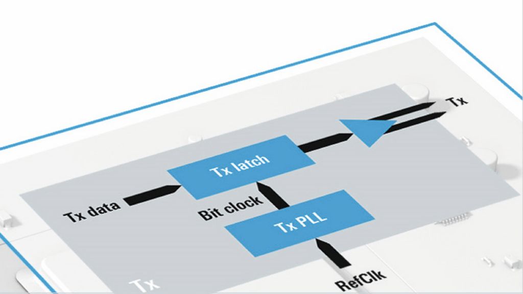
Block diagram of two-stage SerDes PLL
Open Lightbox
Example setup
Example setup
Open Lightbox

Rohde & Schwarz solution

The R&S®FSWP phase noise analyzer and VCO tester has an industry-leading phase noise sensitivity that can be further improved via the R&S®FSWP-B60 cross-correlation and R&S®FSWP-B61 cross-correlation (low phase noise) options.

With the R&S®FSWP-B64 residual phase noise measurements option, the instrument includes an ultra low phase noise signal source for easy additive phase noise measurements.

Alternatively, an external signal source like the R&S®SMA100B RF and microwave signal generator can be used to stimulate the tested PLL. The R&S®SMA100B provides best signal purity and phase noise performance and is scalable with different phase noise performance options.

For most SerDes PLLs and clock synthesizers, the phase noise of the R&S®FSWP-B64 and the R&S®SMA100B is negligible compared to the additive phase noise of the DUT. The phase noise measured by the R&S®FSWP mainly represents the additive phase noise of the DUT.

With the additive phase noise measurement method, included in the R&S®FSWP-B64, the phase noise influence of the stimulus signal can be suppressed even further 1). In contrast to other solutions, there is no need to manually achieve orthogonality with an external phase shifter. The R&S®FSWP automatically takes care of that, setting a new standard in user-friendly additive phase noise measurements.

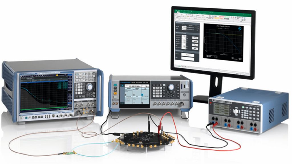
The R&S®SMA100B can also be used to measure the jitter transfer function of the PLL. Via PM modulation (R&S®SMAB-K720 option), artificial jitter is added to the signal source.

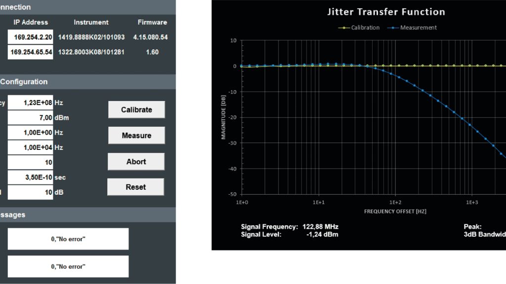
The R&S®FSWP measures the actual jitter at the DUT output and normalizes it to the jitter at the DUT input to determine the jitter attenuation. An external tool can be found in the download section of this application card. Besides R&S®SMA100B (R&S®SMAB-K720 option required), it supports the R&S®FSWP (requires R&S®FSWP-B60 or R&S®FSWP-B61 option) as well as the R&S®FSPN. The tool measures the jitter attenuation at various frequency offsets and provides the jitter transfer function of the DUT, including its peak and 3 dB bandwidth (see screenshots below).

Jitter transfer function: measurement setup
Open Lightbox

Summary

The R&S®FSWP offers the functionality needed to test the additive phase noise of PLLs in high-speed digital designs. The R&S®SMA100B can be used as an external, ultra low phase noise signal source and to measure the jitter transfer function (JTF) of the PLL.

Automated measurement of jitter transfer function
Related solutions