Quadrants of DC power supplies
If current flows into the positive voltage terminal, the power supply acts as an electronic load. It is sinking power instead of sourcing power. Instruments that function both as a source and sink can simulate batteries or loads; they are called two-quadrant (or four-quadrant) power supplies. Rohde & Schwarz offer two- and four-quadrant architecture. The instruments automatically switch from source to sink mode. When the externally applied voltage exceeds the set nominal voltage, current flows into the power supply, which is indicated by a negative current reading.
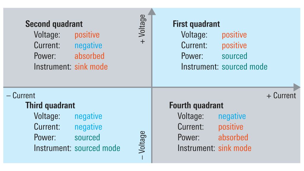
The architecture of power supplies can be fully defined using a Cartesian coordinate system. The four quadrants show all combinations of positive and negative voltage and current. The figure below illustrates a coordinate system with voltage on the vertical and current on the horizontal axis.
As mentioned above, standard power supplies typically generate voltage of positive polarity only (i.e. they work in the first quadrant), for example from 0 V to 20 V. If a power supply can provide either positive or negative voltage at its output terminals without having to switch the external wiring, it is referred to as a bipolar power supply and will work in quadrants 1 and 3, providing voltages from –20 V to +20 V, for example. Such instruments can be used, among other things, to test the characteristic behavior of semiconductors for bipolar voltages across the 0 V point.
Power supplies that can operate in quadrants 1 and 3 typically also offer sink functionality for positive and negative voltages and currents. They can operate in all four quadrants and are referred to as source measure units (SMUs). In the first and third quadrant, current flows out of the voltage terminal; the instrument is sourcing power. In the second and fourth quadrant, current flows into the voltage terminal; the instrument is sinking power.


")
")