Power integrity measurements with R&S®RTP oscilloscopes
Make more accurate power rail measurements.

Make more accurate power rail measurements.
Measuring noise and ripple on power rails with small voltages and increasingly tighter tolerances is a challenge for oscilloscopes. Fast clock and data edges can be coupled onto rails, requiring higher bandwidth oscilloscopes for power integrity measurements.
Using a standard 500 MHz passive probe with a 10:1 attenuation results in additional measurement noise, causing overstated peak-to-peak voltage measurements and masking signal details.
Such a probe does not have sufficient bandwidth to isolate coupled signals. The higher bandwidth of R&S®RTP oscilloscopes allows isolation of coupled signals as shown in the gated FFT image.
Gated FFTs let user zero in on disturbances in the time domain, and see associated tones.
The R&S®RT-ZPR20 and R&S®RT-ZPR40 power rail probes with a 1:1 attenuation ratio have very little noise and sufficient bandwidth to not attenuate critical signal content. Both probes are compatible with R&S®RTP oscilloscopes. The combination results in a measurement system that delivers high-bandwidth, accurate measurements:
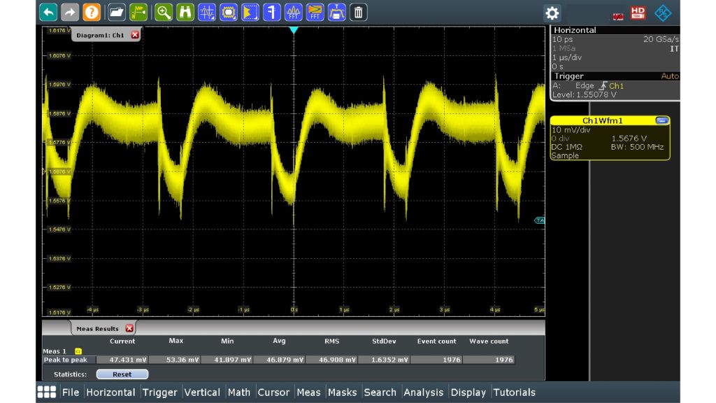
Measurement of a 1.5 V power rail using an R&S®RT-ZP10 10:1, 500 MHz passive probe (50 mV (Vpp), noise masks signal detail).
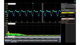
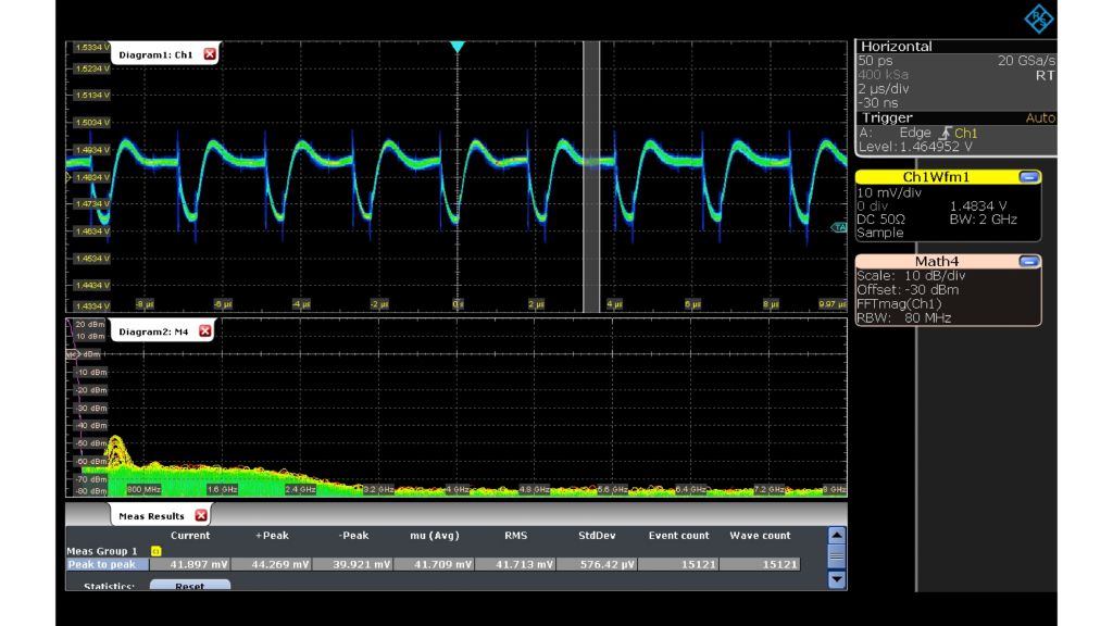
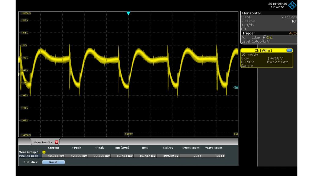
Measurement of a 1.5 V power rail using an R&S®RT-ZPR20 1:1 active power rail probe.
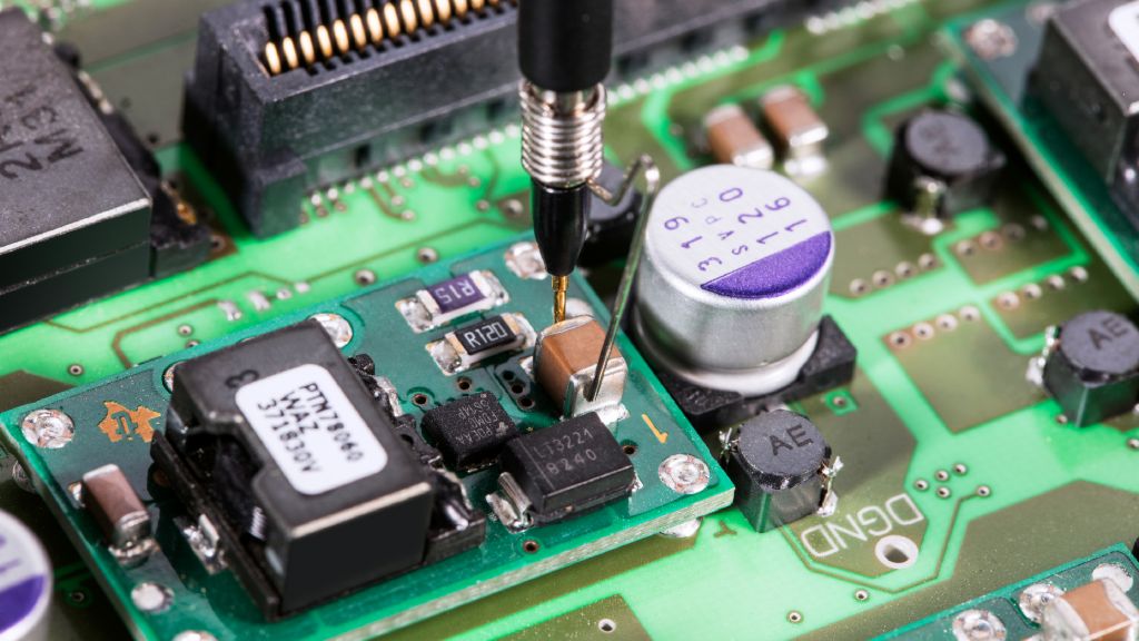
Use the supplied 350 MHz browser with a variety of probing accessories.
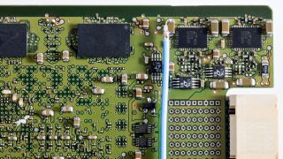
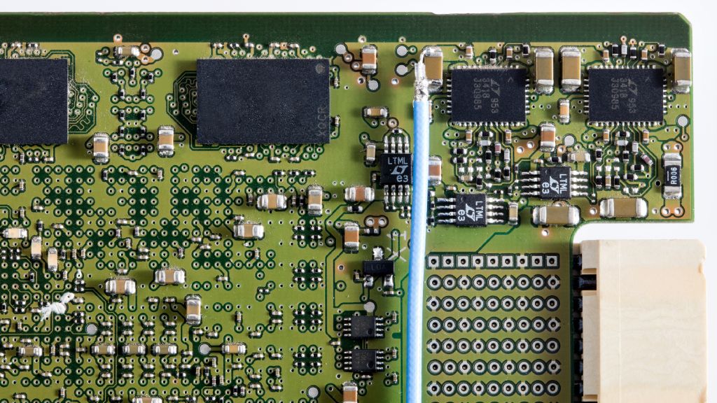
Easily connect using an SMA or solder-in coax pigtail.
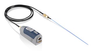
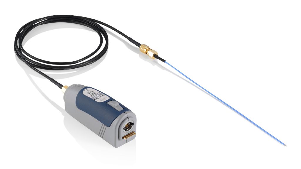
R&S®RT-ZPR20 power rail probe.