Super-resolution DF method

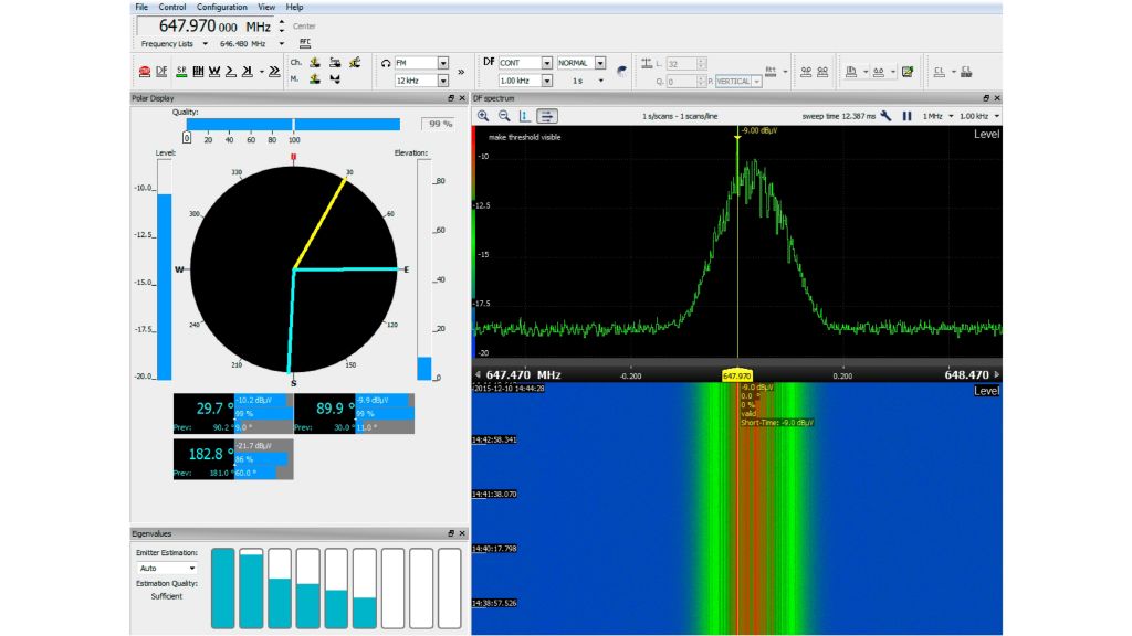
The super-resolution DF method determines bearings of multiple emissions on the same frequency. This method detects signals in the spectrum that are concealed by other emissions. The super-resolution DF method also allows users to take bearings on these emitters, which are undetectable by direction finders that do not feature this method.

Co-channel interference of two transmitters
Open Lightbox

The challenge: co-channel interference

Most radio DF methods can only take bearings on one emitter on a specific frequency occupied exclusively by the transmitter of interest. However, if additional transmitters are operating on the same frequency, direction finding may be impaired (co-channel interference). In this case, the DF result depends on the level ratio of the transmitters. If one of the transmitters is clearly stronger than the others, its direction is displayed with slight DF errors. If the transmitters have similar levels, the DF result is normally incorrect. This applies to all conventional DF principles including correlative interferometer, Doppler and Watson-Watt methods.

Co-channel interference regularly occurs in practice. It is partly even a characteristic of a transmission method:

  • In the HF range, propagation characteristics are continuously changing. Emissions may sometimes travel much farther than originally planned and thus be received in areas where a different station transmits on the same frequency
  • Defective electronic devices may produce electromagnetic interference that occurs on the frequency of transmitters
  • In single-frequency networks such as those used in DAB/DVB, multiple transmitters transmit the same signal on the same frequency from different sites in order to improve the transmission quality
  • Sometimes, specific transmitters are intentionally jammed. In this case, an interfering signal is sent on the same frequency
  • When working with the code division multiple access (CDMA) method, which is used by the Universal Mobile Telecommunications System (UMTS) mobile radio standard, many stations simultaneously transmit signals in the same frequency range. The receivers can distinguish the different signals by means of the spreading code which is superimposed on the message

To allow the bearings of co-channel signals to be taken, Rohde & Schwarz is now making a super-resolution DF method available as an option for the R&S®DDF1GTX high‑speed scanning HF direction finder. The R&S®DDFGTX‑SR option supplements the DF methods already available. The R&S®DDF5GTS high-speed scanning direction finder comes with super resolution even as a standard feature. The super-resolution DF method is able to resolve a wave field with multiple signals on the same frequency. The number and angle of incidence of the waves are first calculated precisely and then displayed. The maximum number depends on the receive frequency, the angle of incidence and the S/N ratio.

Technical background

Conventional DF methods are based on the assumption that the frequency channel of interest has only one dominating wave. However, this may not be the case due to factors such as the following:

  • Spectral overlapping (e.g. CDMA) occurs among thewanted signals being evaluated
  • High-amplitude interferers occur in addition to the wanted signal (e.g. electromagnetic interference)
  • Multipath propagation is present (e.g. reflections from buildings). The DF errors that arise will make the results unusable

Conventional DF technology offers two countermeasures:

  • lf the interferer component is lower in power than the wanted signal component, the DF error can be minimized by dimensioning the direction finder accordingly (by selecting an antenna aperture that is large enough)
  • lf the interferer component is equal to or greater than the wanted signal component, you can take separate bearings of noncorrelated signals using high-resolution wideband direction finders. You can benefit from the spectral differences of the signals

Super-resolution DF methods offer a systematic solution to this problem: They make it possible to calculate the number of waves involved and their angle of incidence. This can be done in different ways. The most accurate method is based on principal component analysis (PCA) of the antenna data. The new R&S®DDF5GTS and the R&S®DDFGTX-SR super-resolution option make use of PCA.