Control loop analysis

Control loop analysis

Control loop analysis for power supplies

The fundamental requirement of the power supply for an electronic device is to maintain a constant output level, despite the load from the device changing. To monitor the output level, the power supply requires near instantaneous feedback of the level, provided by a closed control loop. The power supply shall respond quickly to changes in load, without excessive ringing (oscillating between overshot and undershoot). The quality of the feedback plays a critical role in the performance of the power supply.

Switch mode power supplies (SMPS) are practically the universal choice of power supply design, being small, light, efficient, inexpensive, and suitable for a wide range of input voltage ranges. To investigate whether a switched-mode power supply is operating correctly in varying conditions, measure gain and phase shift in the control loop over a range of frequencies, while inputting a controlled stimulus signal to cause a response in the control loop.

A Bode plot is the tool of choice for power supply control loop analysis, with both the gain in dB and the phase shift in degrees displayed simultaneously. A Bode plot provides information about the performance (speed of regulation) of the loop as the stimulus signal frequency changes, and how close the system is to instability. By comparing the frequency at which the gain crosses the 0dB threshold with the phase, the phase margin shows how much phase margin is left before the system gets into unstable behavior.

An oscilloscop is best suited as measuring instrument, with a Bode plot the most suitable control loop analysis tool for several reasons:

  • Frequency range measurements of the control loop response should be made from near DC to a few MHz, for which oscilloscopes are well suited.
  • The Bode plot results are simple to analyze. Since the gain and phase shifts are displayed simultaneously as the frequency changes, designers can clearly see if their targets for phase margin at the crossover frequency and gain margin at the –180° phase shift are being met to fulfill performance and stability requirements.
  • General purpose bench oscilloscopes offer a level of performance for frequency response measurements that will meet most requirements at a far lower cost than the alternatives. And an oscilloscope can also be used for hundreds of other everyday measurement tasks.

Your power supply control loop test challenge

Getting the happy medium stimulus signal level. If the injection level is too low, the gain will be too high, causing noisy results at low frequencies. On the other hand, some control loops are very sensitive to the injected level; a too-high level results in a too-low gain, causing nonlinearities or large signal effects.

In addition, the necessary stimulus signal level may change with frequency. Typically, a higher signal level is needed at low frequencies, and a lower signal level is needed at higher frequencies.

For control loop signals with a voltage measured in millivolts and a frequency in the kilohertz range, probes must have a suitable low noise floor to support high sensitivity and low signal-to-noise ratios.

Impedance in the loop forward direction must be much larger than in the backward direction in order not to change the behavior of the circuit

Our control loop analysis test solution

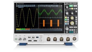
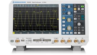
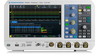
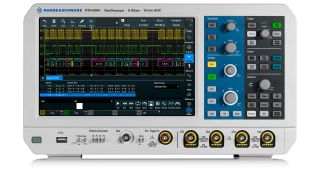
4 families of Rohde & Schwarz oscilloscopes all offer features, functions and performance that make them ideal for frequency response analysis for power electronics: the R&S®MXO4, the R&S®RTB2000, R&S®RTM3000, and R&S®RTA4000.

R&S®MXO4 includes market-leading 4.5 million acquisitions per second, resolution provided by the 12-bit analog-digital converter, and 0.00001 vertical division trigger sensitivity, based on the unique R&S digital trigger, now available in the mid class.

All three RTx oscilloscope families feature a 10.1" capacitive touchscreen with 1280 × 800 resolution, a 10-bit AD converter, 10 s boot time, 16 digital channels (optional) and a wide range of optional instruments such as logic, spectrum and protocol analyzers, arbitrary waveform and pattern generators, and a digital voltmeter.

The R&S®RTx-K36 option for any of these oscilloscopes provides Bode plot analysis; the oscilloscope’s internal signal generator provides the stimulus signal (10 Hz to 25 MHz). Low attenuation probes are available for all these oscilloscopes.

Products

R&S®MXO 4

Next generation oscilloscope for accelerated insight

More information

R&S®RTB2000

More information

R&S®RTM3000

More information

R&S®RTA4000

More information

Benefits of our analysis test solution

No need for an external signal source; the wave form generator built into the oscilloscope provides the stimulus signal (10 Hz to 25 MHz).

Running the analysis to investigate the stability is simple and straightforward, with a Bode plot function. The oscilloscope performs all the necessary parameter changes (with option K36). Simply turn the oscilloscope rotary knob to adjust the stimulus signal frequency, and observe directly on the oscilloscope screen how this affects the gain margin and phase margin.

A rigorous measurement procedure, especially since the optimum stimulus signal level may change with frequency. Use amplitude profiling to optimally match the signal level to the given frequency. Up to 16 steps in the signal level are supported.

Ideal probes for all supported oscilloscopes

Do you have further questions regarding our control loop analysis solutions? Please contact us.

Related documents

Finding irregular effects in control loop design without compromise

The R&S®MXO 5 oscilloscope is a perfect choice for identifying irregular events in the control loop of power converters. Its digital trigger technology enables the user to define complex trigger events to isolate the root cause efficiently.

More information

Converter control supply test

Bode plots are an important tool for verifying control loop stability of switched mode power supplies. Today, this functionality is also provided by oscilloscopes. This application information shows how.

More information

Tips and tricks on stability testing

This application note describes how to measure the control loop stability of switch-mode power supplies. It explains the main concept and practical applications while guiding the user through the process. The measurement is illustrated with a Rohde and Schwarz buck converter reference board, designed with Texas Instruments.

Download now

Webinar: Control loop stability

This webinar deals with measuring the control loop stability of switch-mode power supplies. It discusses the main measurement concept, emphasizing the main topics and describing the measurements from a practical point of view. It also presents proper measurement setups and advises on key solution differentiators.

More information

Knowledge+

Experience the uniquely personalized, high-quality content from the whole Rohde & Schwarz ecosystem - all in a single place. Discover now our knowledge tailored for your needs.

Video center

Get access to interesting videos and webinars about solutions, applications and products.

More information

Download Center

Search the Rohde & Schwarz download center for brochures, datasheets, technical papers, manuals, firmware, software, drivers, and more.

More information

The Rohde & Schwarz Technology Academy

You’re in great hands
Practical knowledge. Industry insight. Real experts. Only with the Rohde & Schwarz Technology Academy.

More information

Related topics

Efficiency testing

More information

EMI debugging and analysis

More information

Switching analysis

More information

Request information

Do you have questions or need additional information? Simply fill out this form and we will get right back to you.

Marketing permission

Your request has been sent successfully. We will contact you shortly.
An error is occurred, please try it again later.