Control loop analysis

Power conversion

Switching analysis

Solutions for power conversion switching analysis

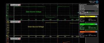
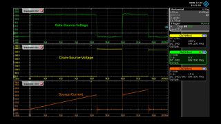
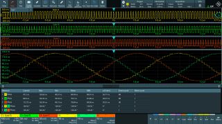
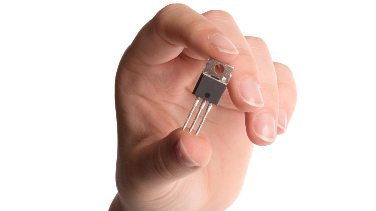
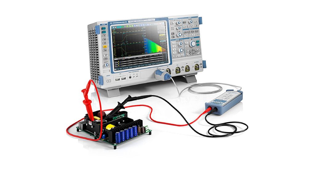
To maximize a power converter’s performance and efficiency, a common practice is to increase the switching frequency. When increasing a power design’s switching speed, the timing characteristics, interactions between high and low side transistors, and undesired outcomes such as shoot-through and excessive EMI must be accounted for. Rohde & Schwarz oscilloscopes, power probes, and software enables power designers to characterize and optimize their designs.

Related contents

AppCard: Increasing confidence of full-bridge converter operation during the design process

Power converters with a full-bridge topology are frequently used in telecommunications and servers that need to be compact, efficient and cost sensitive, making them more complex. Switching patterns for all the main primary switches including synchronous rectifier switches need to be validated after the first protype is built. This complex validation requires proper measurement of switching patterns to prevent catastrophic switching patterns. Expertise and the right measurement tools are essential when identifying unexpected events in the converter switching process.

More information

AppNote: AC-DC converter testing fundamentals

The AppNote will present the most common circuits used for different power levels. The switching mode power supply (SMPS) converter will be the main focus as they are used everywhere in the electronics. Especially the flyback converter design in different flavors are highlighted.

More information

Webinar: Understanding inductor saturation impact on control design

This webinar is intended for engineers who work on power selectronics designs.

More information

Webinar: Fundamentals of switched-mode power supply design with saturated inductors

This webinar is intended for engineers who work on power supply designs.

More information

Webinar: Switching analysis - testing for reliability in power converter design

This webinar is intended for engineers who work on power converter designs.

More information

Step-by-Step guide: Double pulse testing

This step-by-step guide describes the basic concept of double pulse testing (DPT) and the necessary measurement setup and provides an overview of the parameters influencing the measurement. Furthermore, practical tips for carrying out the measurements are presented.

More information

Verification Methods Of Snubber Circuits in Flyback Converters

The demand having a snubber circuit in the power supply topology leads to specific verification methods during the design to obtain a proper and reliable design. These verification methods are the main focus in this AppNote.

More information

Tips & Tricks on Double-Pulse Testing

From designing a test setup to performing accurate measurements. Double-Pulse testing is a standard test-method used in power electronics design. Accurate measurements require a careful design of the test setup and the selection of the right measurement instruments. This application note discusses important aspects of double-pulse test setups as well as how to perform accurate measurements.

More information

AppCard: Increasing test coverage in hard switching half bridge configurations

Power converter and inverter designs for higher power levels are usually based on hard switching half bridge configurations. In such setups, users must pay particular attention to proper switching operations to prevent shoot-through events. Setting up complex real-time trigger conditions using the R&S®RTE and R&S®RTO oscilloscopes increases the test coverage and robustness of converter and inverter systems.

More information

White paper: Gate drive measurement considerations

The more successful a gate driver is in reducing power-up and power-down times, the bigger the headache for accurate measurements. Both choosing the right probe and optimizing the probing technique are significant factors in improving measurement accuracy. This white paper provides guidelines

More information

Webinar: Half bridge and gate drive measurements and techniques

Register and watch the webinar from March 2020: Half bridge and gate drive measurements and techniques with Tom Neville, Technology Manager at Rohde & Schwarz.

More information

White paper: Testing SiC designs

This white paper discusses EMI challenges associated with migrating a design from Si to SiC, test tools and test methodology, along with mitigation and optimization techniques.

More information

Switching analysis on wide bandgap devices

Power conversion designs migrating from silicon to wide bandgap

An increasing number of power converter designs that use wide bandgap (WBG) materials such as SiC and GaN have become commercially available. A WBG semiconductor's fast switching capability must be well characterized to determine the power losses during switching and conduction, to optimize efficiency gains and to avoid negative effects such as shootthrough or excessive EMI. A Rohde & Schwarz oscilloscope with high resolution and low noise combined with a Rohde & Schwarz high-voltage differential probe with superior common mode rejection across frequency allows power converter designers to:

  • Accurately measure power losses during switching and conduction
  • Verify rise/fall time from hundreds of ps to 10s of ns
  • Characterize timing events such as dead time

Read the R&S High-Voltage Differential Probes Factsheet:

Switching analysis measurement equipment

Power conversion designs are switching at higher frequencies and moving toward higher voltages. Making accurate switching analysis measurements requires a high-resolution oscilloscope and high voltage differential probes with top performance, large differential and common mode range, and high common mode rejection across the bandwidth.

Related products

R&S®RTM3000 / RTA4000

See more of your signal with the power of 10. With up to 1 GHz bandwidth, these oscilloscopes offer 10-bit vertical resolution and ultra deep memory for longer acquisitions at full bandwidth.

Product information

R&S®RTO6 oscilloscope

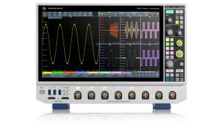
Featuring an updated user interface on a larger, 15.6-inch Full HD touchscreen and straightforward workflows, it speeds up daily measurement tasks. The R&S RTO6 delivers deep insights into designs on the engineer's workbench with state-of-the-art specifications such as an outstanding 9.4 ENOB, an unparalleled update rate of one million waveforms per second as well as a comprehensive toolset of analysis functions.

Product information

R&S®RT-ZHD high voltage differential probes

Designed in-house with superior performance, large differential and common mode range and superior common mode rejection across the bandwidth.

Product information

Related topics

Efficiency testing

More information

EMI debugging and analysis

More information

Control loop analysis

More information

Request information

Do you have questions or need additional information? Simply fill out this form and we will get right back to you.

Marketing permission

Your request has been sent successfully. We will contact you shortly.
An error is occurred, please try it again later.