Fast validation of EMC test sites above 1 GHz with time domain S(VSWR)
The R&S®ZNB vector network analyzer together with the R&S®HF907 double-ridged waveguide horn antenna provides fast and accurate TD SVSWR measurements in line with ANSI C63.25.
The R&S®ZNB vector network analyzer together with the R&S®HF907 double-ridged waveguide horn antenna provides fast and accurate TD SVSWR measurements in line with ANSI C63.25.
EMI test sites for radiated emission measurements in the 1 GHz to 18 GHz frequency range rely on free space conditions to minimize the influence of reflections on the received signal. Practically, this is achieved using shielded enclosures that are fully lined with RF absorbing material (fully anechoic room, FAR).
Site validation determines the deviations from the free space conditions that are necessary to meet the acceptance criterion for performing EMI compliance measurements in a FAR. This site validation is performed by measuring the site voltage standing wave ratio (SVSWR), which is the ratio of the maximum received signal to the minimum received signal caused by interference between direct (intended) and reflected signals. There are two different approaches for showing compliance with the acceptance criterion:
In principle, both methods consist of a series of response measurements between a pair of antennas and use the same acceptance criterion of SVSWR ≤ 6.0 dB. For the CISPR method, it is necessary to vary the distance between the two antennas six times to change the phase relationship between the direct antenna response and the reflections. The ANSI time domain method works without the need to move antennas. This is achieved through a complex transmission measurement (S21) using a vector network analyzer (VNA) and time domain transformation of the frequency domain data.
The result shows the impulse response between the two antennas. Since the direct antenna-to-antenna response is related to the shortest distance, the earliest pulse is the direct antenna response. Reflections from the test site are from farther away and come later. It is therefore possible to use time gating to separate the direct antenna response from reflections and to calculate the TD SVSWR.
R&S®ZNB vector network analyzers equipped with the R&S®ZNB-K2 time domain analysis option offer the measurement function for measuring the TD SVSWR in line with ANSI C63.25. For a validation range of 1 GHz to 18 GHz, set the VNA to harmonic frequency grid with a start frequency of 500 MHz, a stop frequency of 19.7 GHz, a step size of 1 MHz, output level of 0 dBm and bandwidth of 1 kHz.
Note: The additional frequency range (above and below the frequency of interest) is needed to account for the windowing effect of the time gating process where the data at the band edges is unreliable.
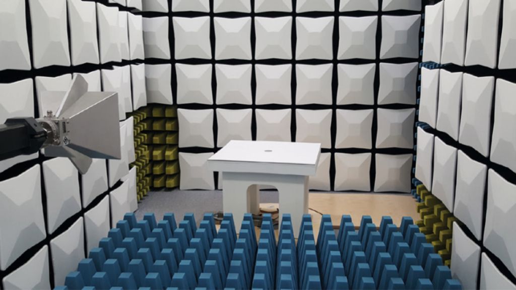
Perform a full two-port VNA calibration at the ends of the cables used for connecting the transmit and receive antennas. Connect the cables to the antennas and place the transmit antenna on the turntable at the first measurement location and polarization (see figure).
Perform a transmission measurement and check the sensitivity of the setup. A signal-to-noise ratio of at least 20 dB needs to be achieved. Activate the TD SVSWR measurement function in the VNA’s time domain menu.
Note: The Hann window function is used by default. Set the gate span so that only the direct antenna response and any ring-down time associated with the antennas are within the gate span.


R&S®ZNB TD SVSWR configuration menu and display of results
Note: The purpose of the gate is to retain the direct time response between the antennas and to suppress all other responses. It is sufficient to set the time gate center to the peak of the main response, and the gate span symmetrically around the peak to a value of twice the antenna ring-down time. For the R&S®HF907, use a gate span of 8 ns.

TD SVSWR measurement positions in a horizontal plane
Perform an S21 sweep and export the trace as formatted data for further evaluation. Repeat the procedure for all other transmit antenna positions and polarizations.
Note: All positions F (front), R (right), L (left) and C (center) are measured at a height of 1 m above the bottom of the test volume. The front position is additionally measured at a height of 2 m. The center position is optional if the diameter of the volume is less than or equal to 1.5 m.
The time domain method provides more information on the test site in addition to demonstrating conformity with the site validation requirements. For example, you can use the time domain impulse response view to identify the location of areas in a FAR where additional or better quality absorbers are needed. The antenna response on an ideal site would show a single pulse (the direct antenna-to-antenna response). Therefore, any large unwanted reflection can easily be identified. In addition, the distance from the antenna can be displayed since time and distance are related by the speed of light (c ~ 3 × 10⁸ m/s) in free space.
The R&S®ZNB20 two-port vector network analyzer with its time domain analysis functions together with the R&S®HF907 double-ridged waveguide horn antenna is the ideal solution for fast and accurate site validation measurements using the TD SVSWR method in line with ANSI C63.25.
The motivation to use the ANSI time domain method is that it takes less time to perform the site validation of an EMC test site for above 1 GHz testing than with the CISPR method, with the added benefit of indicating where the site or chamber is imperfect.
Related products