Shorten power electronics development using an oscilloscope for EMI debugging

Oscilloscopes are the workhorses for power electronics engineers. With powerful and easyto- use FFT analysis capabilities, their application fields extend to EMI debugging – and that saves a lot of time and money. A typical task is verifying the effectiveness of an EMI filter – early in the development phase.

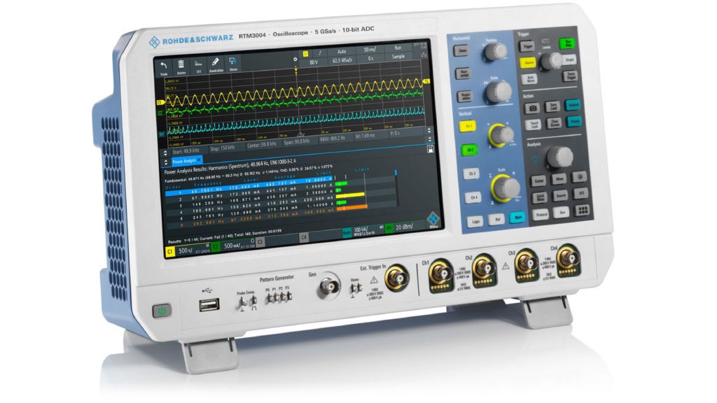
Shorten power electronics development using an oscilloscope for EMI debugging - RTM3004

Your task

Conducted emission testing is a mandatory measurement at the end of each design process of a switching mode power supply (SMPS). The developer has to verify that the product is compliant with the applicable standard before it can be released on the market. Full compliance testing requires a test chamber and a suitable EMI receiver. If the product falls outside the limits of the standard, it may be necessary to modify the power supply and that can greatly affect many parts of the SMPS, e.g. EMI input filter, PCB design, concept decisions like selection of a suitable switching frequency. This can significantly impact the time to market. It is often necessary to partially redesign the product. This risk can be drastically reduced by performing the conducted emission tests in an earlier stage of the development cycle. For precompliance testing, you do not necessarily need a chamber, but you do need an instrument that is able to measure the spectrum of the power supply input and output lines in a comparable manner. This can be a spectrum analyzer but also an oscilloscope.

Shorten power electronics development using an oscilloscope for EMI debugging - Oscilloscope

T&M solution

Rohde & Schwarz oscilloscopes offer a powerful, easy-touse FFT analysis functionality to measure the magnitude of the frequency component. Users are able to see the time domain related signals at the same time and can therefore correlate unwanted spectral emissions with time domain events. This makes these oscilloscopes powerful standalone instruments for performing early conducted emission tests on power electronics designs. This is particularly helpful when no dedicated equipment such as an EMI receiver is available in the R&D lab to support the precompliance measurement during the design phase.
The earlier EMI compliance is taken into account, the more likely it will not become an issue at the end of the development process. Uncovering an EMI problem early on is less costly and easier to fix. Since oscilloscopes are typically the main instrument used during hardware development and system testing, they are a valuable tool for EMI related tests in R&D.

Test setup
To measure conducted emissions of a power supply, a line impedance stabilization network (LISN) is required to decouple the device under test from the external power supply. The coaxial output of the LISN has to be connected to the oscilloscope with a coaxial cable with 50 Ohm input impedance activated at the oscilloscope to ensure proper matching. On the oscilloscope, the following steps have to be executed to measure the spectrum:

  • Activate the FFT and configure the minimum and maximum frequency and the resolution bandwidth.
  • Adjust the vertical sensitivity in the time domain window such that the input channel is not overdriven when the device under test is powered.
  • Switch off the power to the DUT to make a reference measurement. This makes sure that you know the noise floor of the setup and that this noise does not come from the DUT.
  • Switch on the power again and make a measurement. Verify against known conducted emission limits for the DUT. Take into account any additional attenuation due to the LISN.
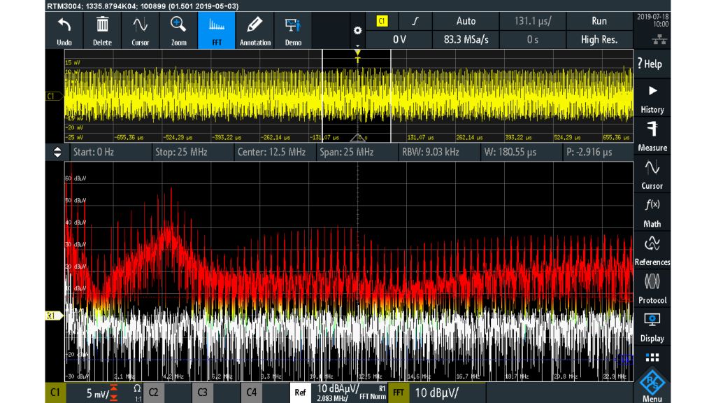
EMI spectrum without input filter

Case study – effectiveness of the EMI filter
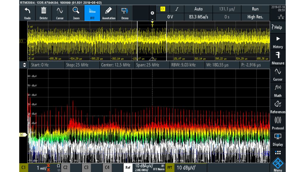
The following two screenshots illustrate a conducted emissions measurement with the R&S®RTM3000 oscilloscope – without and with an EMI filter.

Channel 1 displays the measured time domain signal connected to the LISN. Due to the LISN, this signal is attenuated by a factor of 10 dB, which has to be taken into account when comparing measured values with emission limits. The bottom window shows the spectrum in dBuV on the input terminal of the power supply. Without an EMI filter, the noise spectrum generated at the input of the DC/DC converter is clearly visible. In contrast, the measurement with an EMI filter shows that the conducted emissions on the input line are effectively attenuated.
For some frequencies, up to 30 dB attenuation is visible.

EMI spectrum with input filter

To verify emissions in the lower frequency region, the user has to repeat the measurement with a focus on the lower frequencies.

Summary

The FFT functionality of Rohde & Schwarz oscilloscopes is a powerful feature that enables designers to debug conducted emissions of power supplies. Since the oscilloscope is a standard measurement instrument for power electronics design, it can save a lot of time and money by also using it to evaluate EMI early in the development phase. This makes it more likely to achieve EMI compliance without an essential redesign of the product after failed compliance testing.

Related solutions