Testing IoT designs with the R&S®RTO2000 - Focus EMI Debugging
Focus EMI Debugging
Focus EMI Debugging
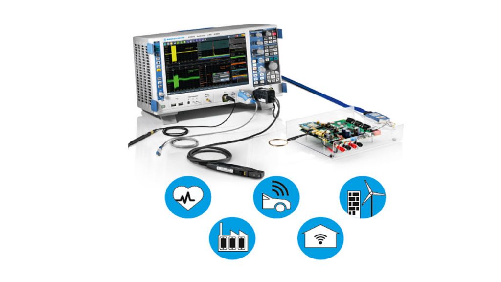
The need for Internet of Things (IoT) solutions can arise fast. In most cases, wireless communications modules are added to an embedded design. When designing and debugging IoT systems, manydifferent measurements need to be performed. Since developers are very familiar with using an oscilloscope for voltage and time measurements, they also want to use it to for all other necessary measurements. And now they can – with the R&S®RTO2000 multi-domain oscilloscope.
| Typical measurement tasks during the development of wireless embedded IoT systems that can be accomplished with Rohde & Schwarzoscilloscope solutions | ||
|---|---|---|
| Task | Need | Product feature |
| Validation of power management |
|
|
| Chipset interconnection testing |
|
|
| Testing of wireless modules |
|
|
| Validation of overall system |
|
|
| EMI debugging |
|
|
Analysis of a wireless module’s data capture, processing and communications timing
The upper screenshot displays an IoT module’s GSM connection time-correlated to power consumption and data traffic on the modem interface. The RF and power supply voltage and current are measured on the analog channels. The digital channels acquire the module’s modem interface communications via UART and decode the protocol. The spectrum of the GSM bursts is shown on the top right.


Conducted emission test with a mask defined in the spectrum.
EMC debugging of an power supply
The built-in fast FFT the spectrum mask test and advanced spectrum features such as the log display allow relative measurements of EMC emissions. The example conducted emission on the right side shows the conducted emission test with a line impedance stabilization network (LISN). This makes it easy to determine EMI protection measures and prepare compliance measurements.
The table shows a suggested configuration for IoT measurements. This configuration can be extended depending on your needs, e.g. by adding custom decoding for NRZ/Manchester protocols, I/Q acquisition and vector analysis software, even after the initial purchase. A broad portfolio of active and current probes is also available.
| Designation | Type | Order No. |
|---|---|---|
|
Oscilloscope, 2 channels, 3 GHz bandwidth, 10 Gsample/s sampling rate per channel, 50 Msample sampling memory per channel |
R&S®RTO2032 | 1329.7002.32 |
| I2C/SPI Serial Triggering and Decoding | R&S®RTO-K1 | 1329.7260.02 |
| UART/RS-232 Serial Triggering and Decoding | R&S®RTO-K2 | 1329.7277.02 |
| Spectrum Analysis | R&S®RTO-K18 | 1329.7425.02 |
| Mixed Signal Option, 400 MHz, 5 Gsample/s, 16 channels | R&S®RTO-B1 | 1304.9901.02 |
| Probe Set for E and H Near-Field Measurements, 30 MHz to 3 GHz | R&S®HZ-15 | 1147.2736.02 |
Related products