Variants on the Zeroth Embodiment

Measurement-aided Doherty amplifier design - chapter 3

Doherty amplifier variants

The following are variations on the basic concept, which might be more appropriate for some applications.

Commonly used variants, plus their hybrids, include:

  • Multiple gain stages
  • Intentionally dispersive splitter
  • Programmable splitter
  • Bias Modulation (Not to be confused with Supply Modulation, which introduces a 3rd efficiency enhancement technique to Doherty.)
  • RF Envelope Shaping
  • Digital Doherty

Variations of the basic concept:

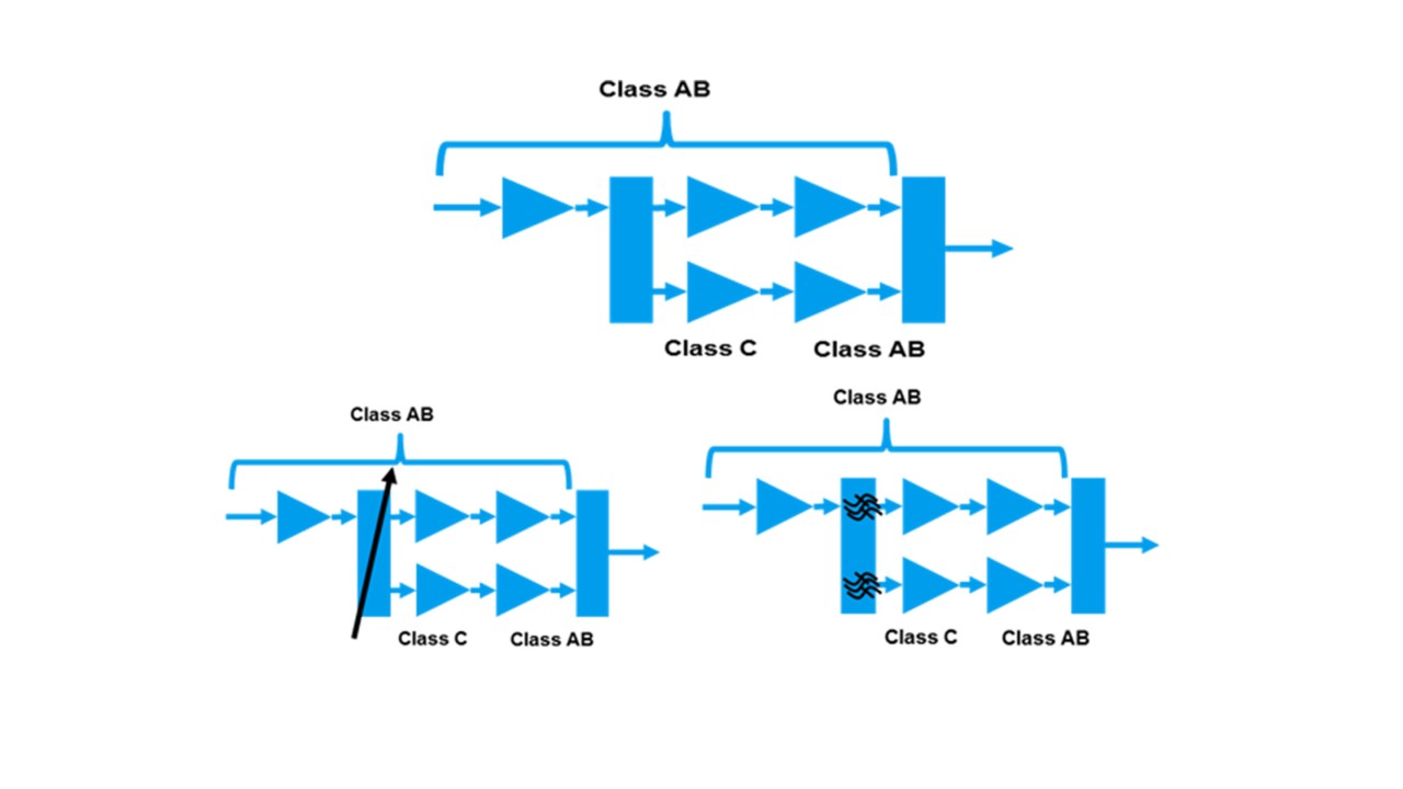
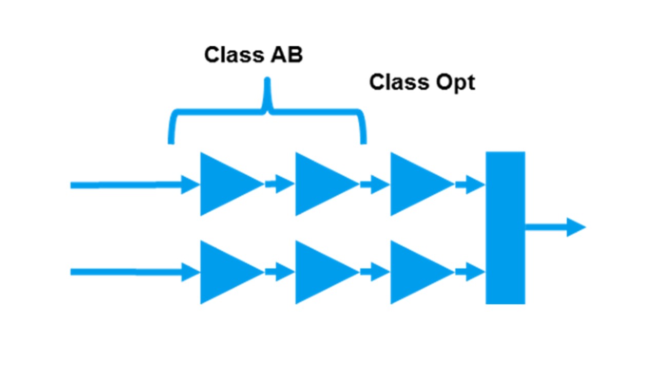
Doherty amplifier cascading variant

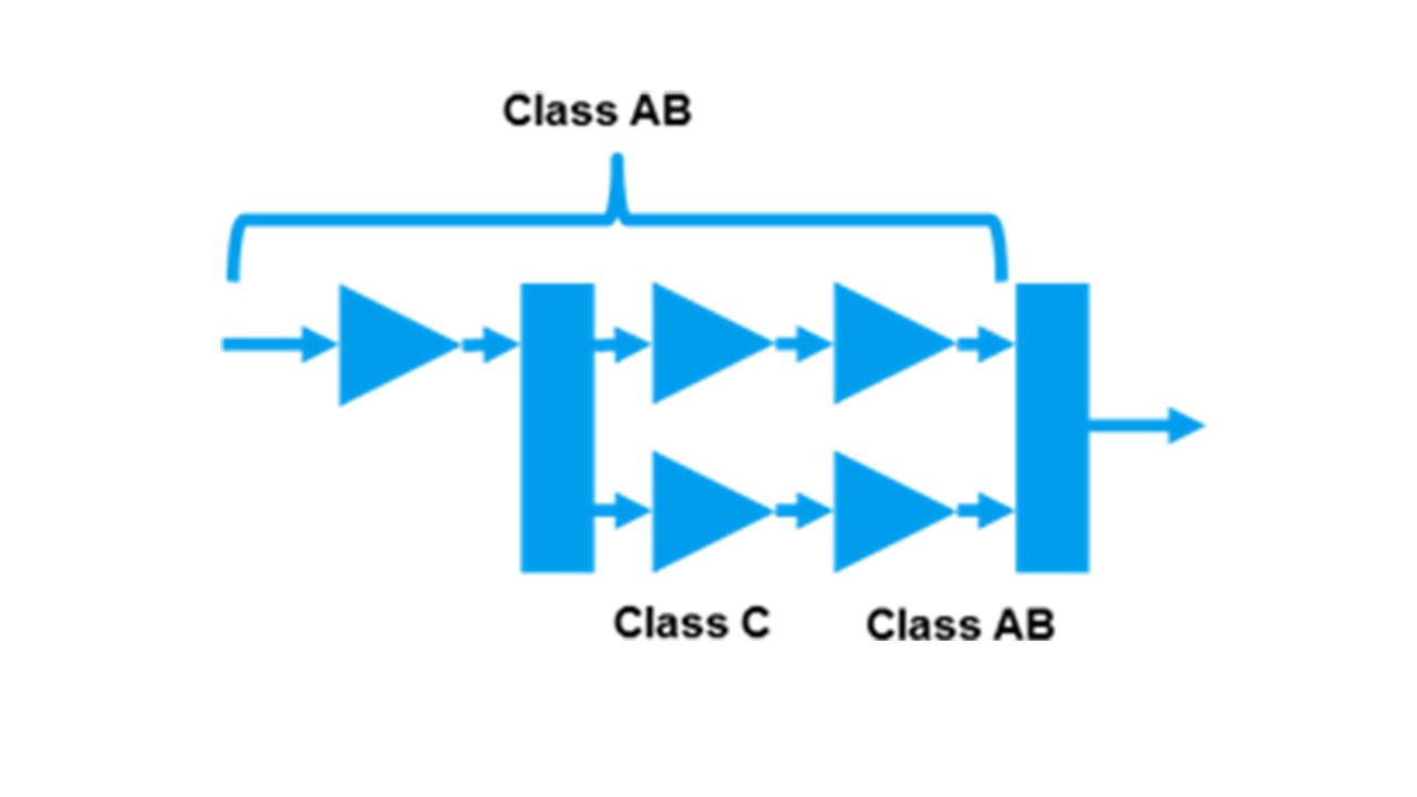
Cascading

Cascading two or more stages can free up bias selection of the final stage, but renders the design liable to greater amplitude/phase dispersion and variation.

Cascading two or more stages, inside the split/combine section, can free up bias selection of the final stage. This can increase both output power and efficiency.

The downside of this solution is the increased number of devices, and their associated gain/phase variations. This effect might even be sufficient to reverse the improvements achieved through common biasing.

Doherty amplifier adjustable splitter variant

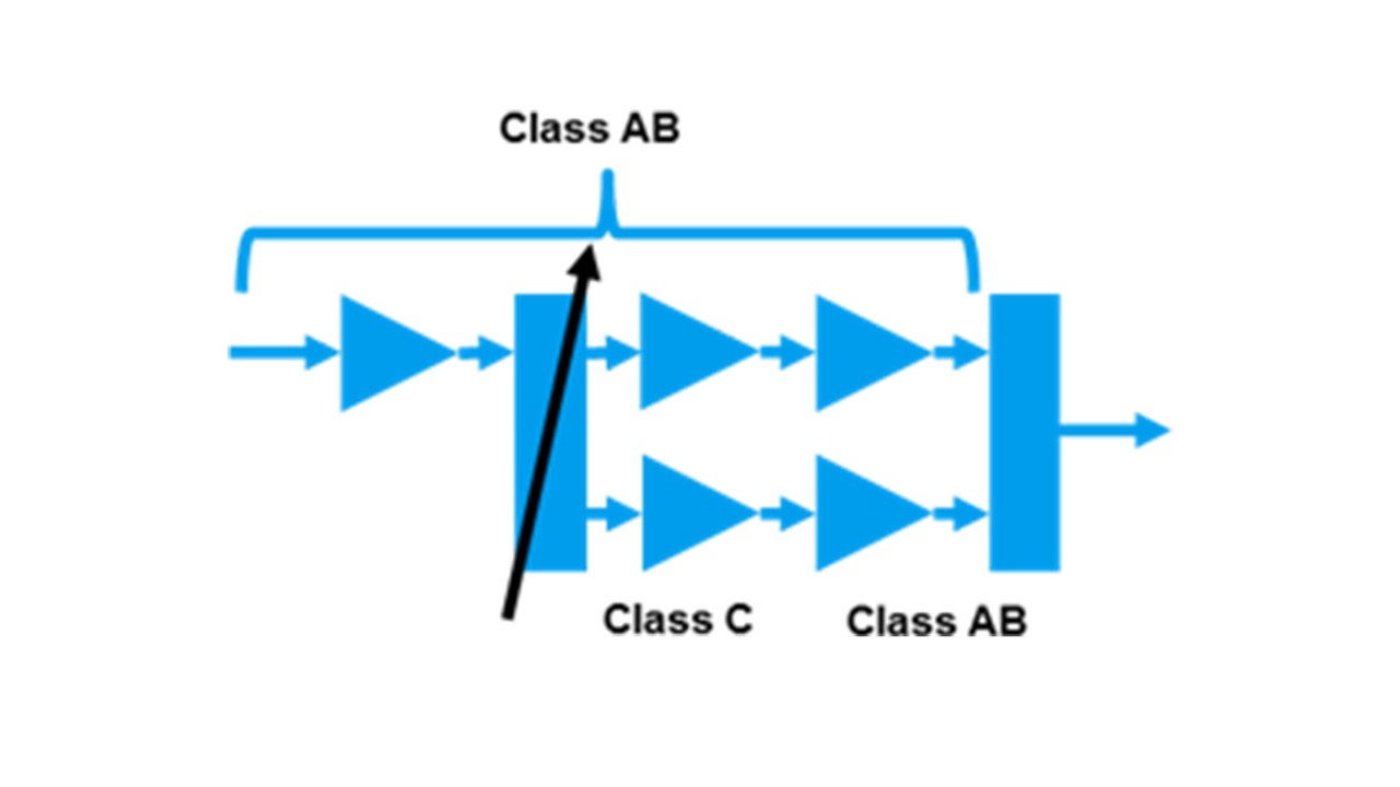
Adjustable splitter

With an adjustable splitter, higher performance can be achieved across the bandwidth. But, this bandwidth improvement cannot be achieved instantly or simultaneously, plus adaptation might be needed.

Combining the simple cascade with an adjustable input splitter (intended to provide different splitting for different frequencies) can improve matters, over the "Cascading" case.

Depending on the splitter design however, the improvements may only be applicable to a narrowband. Furthermore, adaptation of the split ratio for different frequencies might require additional control and monitoring circuitry.

Doherty amplifier adjustable splitter variant

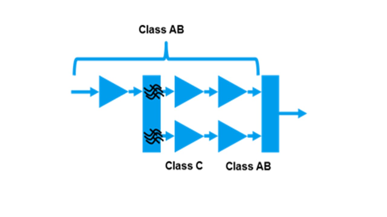
Dispersive split

A (frequency) dispersive split design is one which intentionally provides intentionally different amplitude and phase splitter values at different frequencies. In a simple design, this might utilize a high pass structure in one path, and a low pass structure in the other. For example, this might provide the typical 90 degree phase difference in the middle of the band, but 80 degrees and 100 degrees at the low- and high-band edges respectively.

Doherty amplifier digital doherty variant

Arguably, the Magnum Opus implementation is the so-called Digital Doherty

This architecture is characterized by an input split which stretches back into the digital domain, prior to digital-to-analog conversion (DAC). The ability to apply digital signal processing (DSP) techniques to the signal applied to both paths provides for a potentially unsurpassable performance elicitation from a given piece of RF hardware. Compared to the Zeroth implementation, it can offer 60% greater output power, 20% more efficiency, 50% more bandwidth without degrading predictable linearizability.

Ask the expert

Gareth Lloyd

Gareth Lloyd

Gareth Lloyd graduated from the University of Leeds in 1994 with a degree in Electronic & Electrical Engineering. Gareth has worked in various engineering and management roles, in different industries, for major companies including Ericsson, Huawei, ZTE, TriQuint and Andrew Corporation. Gareth joined Rohde & Schwarz in 2015, as a Senior Expert. His primary work focus is performance differentiated radio front-ends (RFFE).

Ask Gareth

Related chapters

Request information

Do you have questions or need additional information? Simply fill out this form and we will get right back to you.

Marketing permission

Your request has been sent successfully. We will contact you shortly.
An error is occurred, please try it again later.