Analyze pulse width modulated signals
With a Rohde & Schwarz oscilloscope

With a Rohde & Schwarz oscilloscope
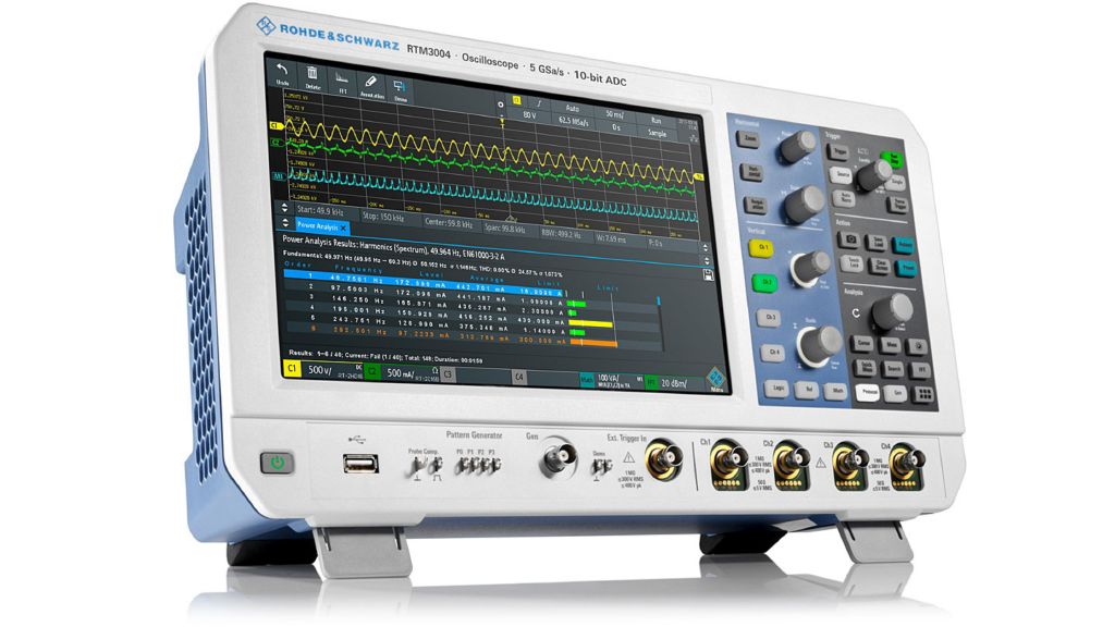
Pulse width modulation (PWM) is a commonplace technique for efficiently driving switched mode supplies at a fixed frequency. This applies to many types of power supplies in industrial control systems, power electronics and digital communications. PWM is therefore a particularly widespread technique used in designing D/A converters, e.g. class D audio amplifiers, DC/DC power supplies and inverters, e.g. variable frequency drives (VFD) of DC motors and three-phase motor drives. Especially difference signals in bridges or multiphase motor drives exhibit bipolar, double pulse features and challenge engineers every day in development and testing.
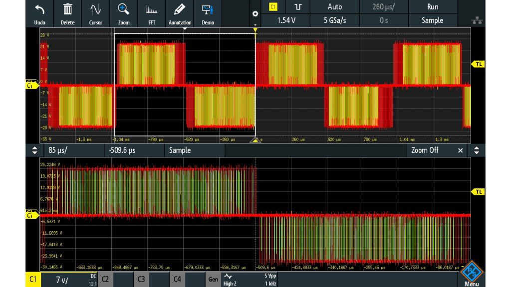
Bipolar PWM signal captured with width trigger on negative going pulse (displayed in waveform color rainbow; red indicates frequent occurrences)
A quick and easy way to get a high-level picture of a PWM signal is to use the persistence display capability of your oscilloscope. Using persistence can give you an overview of the type of pulse widths you are dealing with in your signal. In addition, color grading shows where most waveform activity is located.
However, persistence and color grading do not provide any analysis insight. Is the period modulated in addition to width? How often does the modulation cycle repeat? How many widths of each value occur? Such knowledge is essential when developing various electronic modules such as buck converters, which are used in power supplies, in the supply voltage of processors or for battery chargers.
To gain these insights, you need to use more insightful analysis techniques.
The track function of the R&S®RTM3000 and the R&S®RTA4000 oscilloscopes can demodulate the PWM signal and extract the underlying modulation signal in a track waveform. The track waveform is composed of measured values in the temporal order they were recorded during an acquisition. This analysis tool plots the results of any given value against time, giving you a very clear view of how PWM parameters change when measured for a relatively long period. This makes it possible to assess correct tracking and linearity in PWM regulators/controllers.
The standard in the R&S®RTM3000 and R&S®RTA4000 track function integrated in the math allows you to define an upper (unipolar) and a lower (bipolar) threshold for your demodulated signal.
Math includes as standard the following track analyses:
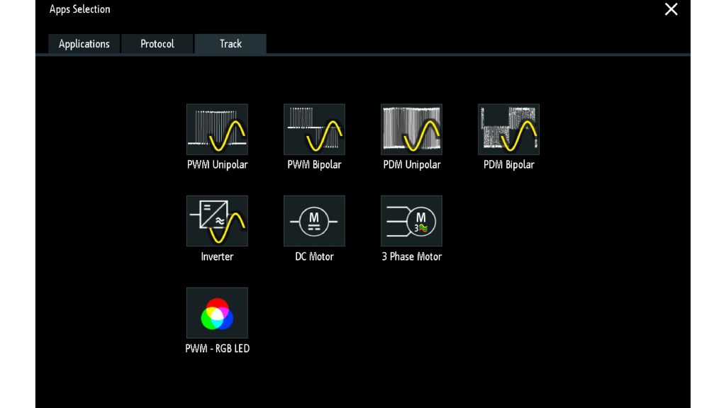
Sample demodulation types make it easy to match your application
Accurate PWM measurements depend on good probing. Most oscilloscopes usually come with 10:1 passive probes. With these, it can be ambiguous to find a meaningful ground reference point, for example when measuring the difference between two signals that may not be connected to earth ground. For these measurements, differential probes are recommended, such as the R&S®RT-ZD10. Depending on the application and environment, the voltages can vary considerably and can be up to the kV range. The R&S®RT-ZHD probes designed for voltages up to 6 kV are best suited for these environments.
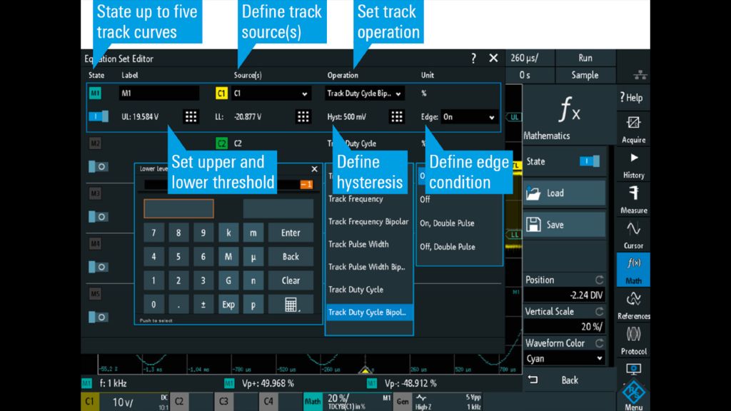
Operation menu for track functionality
Instrument setup
After connecting the oscilloscope to the circuit under test, use the oscilloscope application dialog to access the track tab, which contains a variety of demodulation types.
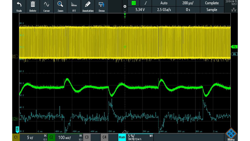
Demodulation of a unipolar PWM signal of a buck converter with measurements on C1 switch mode, C2 output
Measurement results
Using the track function in the math menu allows you to demodulate the PWM signal and displays the waveform additionally as a math trace. This makes it possible to display up to five track curves simultaneously.
Based on the extracted track waveform, further analysis can be performed. The track functionality in the R&S®RTM3000 and the R&S®RTA4000 enables you to put each cursor set on the track waveform and apply all available math options to it. You can also employ all available measurements such as RMS or frequency (get information about rotation frequency) on the track waveform and view the statistical evaluation of each measurement.
After performing measurement and analysis steps, gain a deeper view regarding, for example, how often a modulation cycle repeats or how many widths of each value occur. Use the insight to find errors in the control algorithm, to investigate the controller behavior or to observe the startup and shutdown behavior. This will give you an extensive understanding of what is really going on in your PWM signal.
For reporting, you can easily and quickly save screenshots, waveforms, statistics or the entire setup to a USB device or via LAN to the PC.
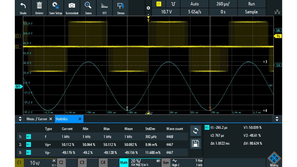
Demodulation of a bipolar PWM signal with measurements, statistics and cursors
The track functionality of the R&S®RTM3000 and the R&S®RTA4000 oscilloscopes is a great feature for displaying any varying PWM signal versus time in various applications.
It will provide detailed information about the PWM signal for each single cycle and show any unexpected anomalies. Combined with additional measurement capabilities, a 10 bit ADC, deep memory and segmented memory, the R&S®RTM3000 and the R&S®RTA4000 offer a cost-effective and time-saving solution. Both instruments give engineers flexibility in designing D/A converters, DC/DC power supplies and inverters, e.g. VFD of DC motors and threephase motor drives.