Testing uplink accuracy for WLAN IEEE 802.11ax

Rohde & Schwarz signal generators and spectrum analyzers can be used to test IEEE 802.11ax stations in terms of uplink accuracy requirements. Measurements such as residual carrier frequency error and timing accuracy of HE TB PPDU transmissions are supported.

Your task

Wireless connectivity, which has been successfully implemented all over the world, has gone through some tremendous evolutionary steps. Legacy WLANs have introduced physical layer functionality such as wider bandwidth, MIMO and higher-order modulation schemes, achieving higher throughput. To tackle the challenges of crowded networks, the upcoming new IEEE 802.11ax standard will now focus on increasing overall efficiency. The most important change is the introduction of OFDMA for uplink and downlink, which offers more flexibility but also increases complexity. To ensure the success of future WLAN IEEE 802.11ax devices and services, it is obvious that new tests must be conducted to verify interworking.

Especially for the OFDMA uplink, also called high-efficiency trigger-based (HE TB) PPDU, it is critical that all devices operate within the defined limits. Since multiple stations (STA) participate in the HE TB PPDU transmission, the participating STAs have to synchronize transmission time, frequency, sampling clock and power to mitigate interference issues.

HE TB PPDU transmission (in the uplink) is preceded by a trigger frame sent by the access point (AP) (in the downlink). This trigger frame is sent to all stations to coordinate the uplink transmission. The trigger frame includes information such as payload length, bandwidth, resource unit (RU) allocation and modulation scheme. Each STA needs to synchronize its LO frequency to the frequency of the trigger frame. Further, the transmission of the uplink signal must start after a specified short interframe space (SIFS) time interval after the end of the trigger frame.

Since an STA occupies only a small portion of the available bandwidth (OFDMA), it must ensure that unwanted emissions within the channel stay below certain limits in order not to interfere with other stations.

T&M solution

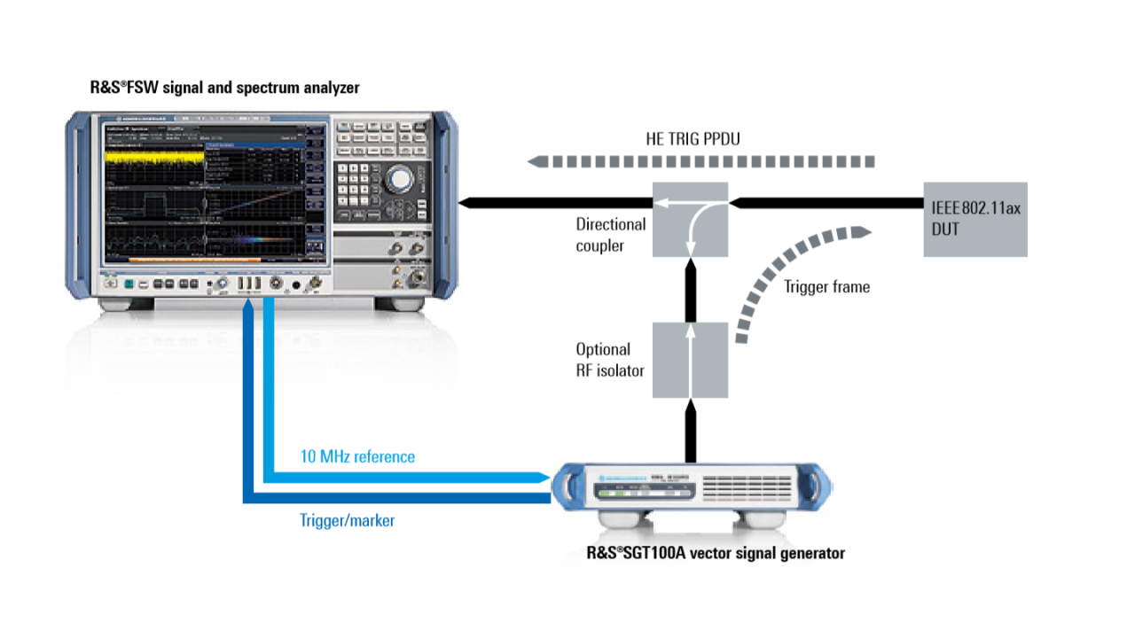
Signal generators and spectrum analyzers from Rohde & Schwarz generate the required trigger frame and analyze the STA’s response. For example, an R&S®SGT100A vector signal generator sends a userdefinable trigger frame to the STA under test. The STA responds by sending an HE TB PPDU frame that is routed to the R&S®FSW for analysis. Both T&M instruments share a 10 MHz reference signal for frequency synchronization. The R&S®SGT100A additionally provides a trigger signal to the R&S®FSW for time synchronization. The user can fully configure the trigger frame, including all “common info” and “user info” fields needed to specify information for all stations, e.g. payload length, and for the individual STA under test, e.g. RU allocation.

CFO error The IEEE 802.11ax stipulates that an STA needs to precompensate for carrier frequency offset (CFO) error to prevent intercarrier interference between different participating STAs. After compensation, the absolute value of the residual CFO error with respect to the trigger frame must be less than 350 Hz. For this test, the signal generator emulates the AP sending trigger frames. Due to the shared 10 MHz reference signal, there is virtually no frequency error between the signal generator and the spectrum analyzer. The spectrum analyzer can therefore precisely measure the residual CFO of the STA with respect to the trigger frame.

Figure 1 Timing accuracy
Open Lightbox

Timing accuracy

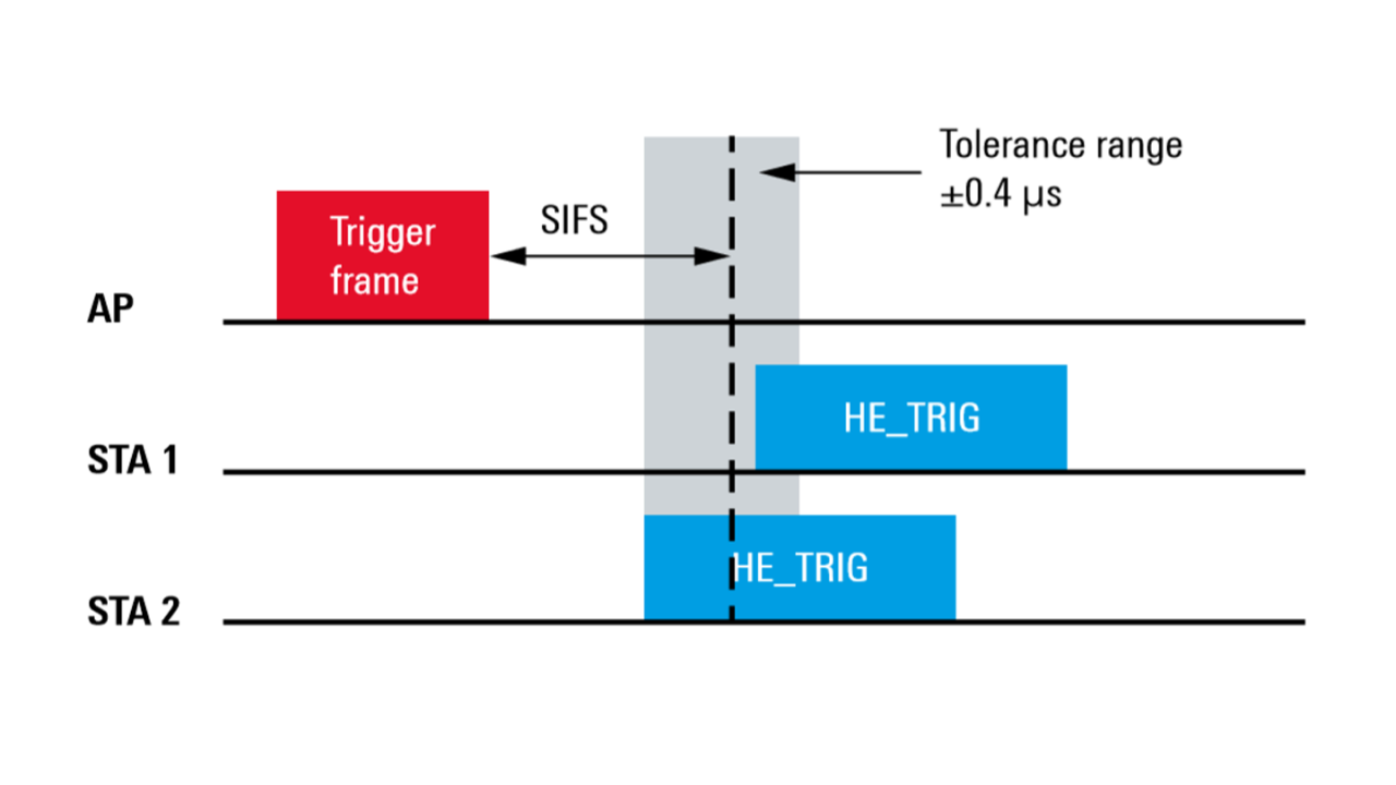
An STA participating in an HE TB PPDU transmission needs to start transmission after a specified SIFS time interval after the end of the trigger frame. The STA must fulfill a timing accuracy of ±0.4 μs for the SIFS, i.e. the transmission must start within a time period of SIFS ± 0.4 μs after the end of the trigger frame (see Figure 1).

For this test, the signal generator again sends a trigger frame. The signal generator also sends the spectrum analyzer a trigger signal that marks the end of the trigger frame. The spectrum analyzer can therefore precisely measure the time elapsed between the trigger frame and the start of the HE TB PPDU transmission. The measured time minus the specified SIFS (i.e. 10 μs in the 2.4 GHz band and 16 μs in the 5 GHz band) gives the timing error of the STA.

Figure 2 Unused tone error
Open Lightbox

Unused tone error

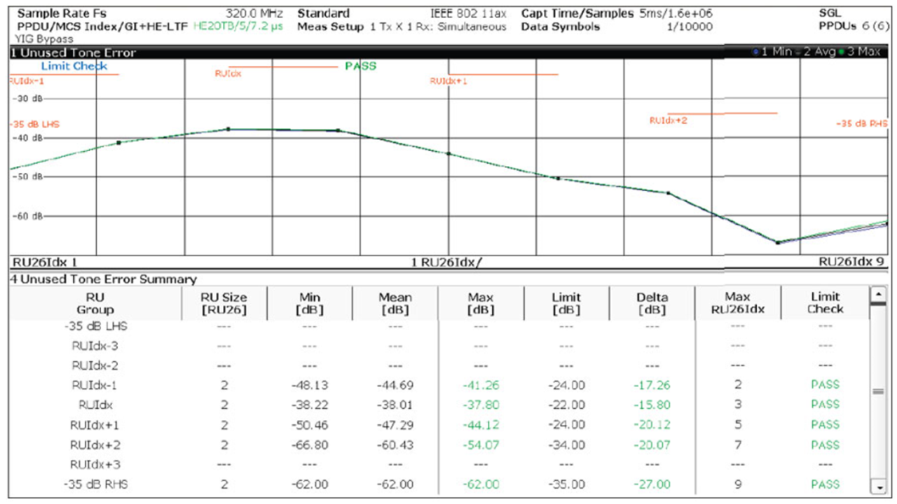
In order not to interfere with other stations, the STA’s unwanted emissions within the channel must stay below specified limits (see Figure 2).

For this test, the R&S®FSW offers automated measurements for the unused tone error, including automated limit line calculation. This is convenient since the limits depend on the modulation scheme as well as on the RU size of a station under test. Again, a trigger frame from the signal generator is needed to stimulate the transmission.

Measurement setup for testing HE TB PPDU transmit requirements