Radar remote site maintenance measurement with the R&S®ZNH

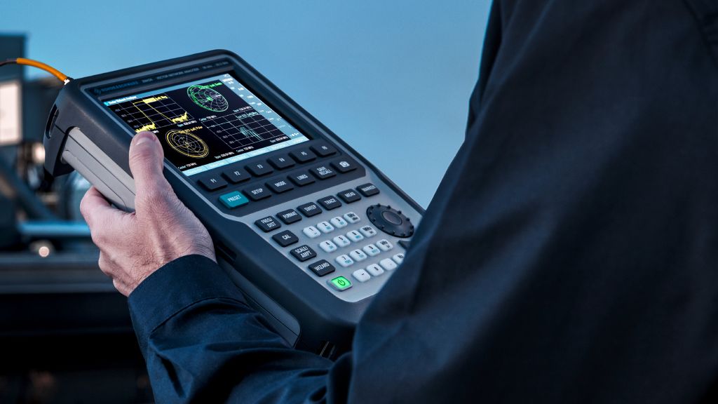
A radar system typically operates 24 hours with minimal downtime. Maintaining the operation of such a system requires fast identification of any defects in the system components. The R&S®ZNH handheld vector network analyzer helps field engineers quickly and reliably maintain radar systems to minimize downtimes.

Radar remote site maintenance measurement with the R&S®ZNH

Your task

Radar systems in remote sites are often exposed to severe weather conditions, making physical damage to system components unavoidable, degrading performance over time and causing unwanted failures to occur. To reduce downtime, engineers frequently perform routine maintenance checks on system component performance. Troubleshooting and identification of radar faults must be carried out quickly and accurately. The table shows some of the measurements performed during the maintenance period to ensure optimal system performance.

Common measurement parameters
Open Lightbox

A battery-powered handheld instrument with multiple functions is better for carrying out these measurements and eliminates the need to carry multiple tools on site. In addition, a ruggedized, fanless design is a must for working in remote locations.

Rohde & Schwarz solution

The two-port R&S®ZNH vector network analyzer simplifies maintenance tasks at remote sites up to the Ku band. With integrated distance-to-fault (DTF), power meter, ratio/wave quantities and pulse measurement functions, the lightweight R&S®ZNH helps engineers to perform maintenance tasks and quickly restore a down system.

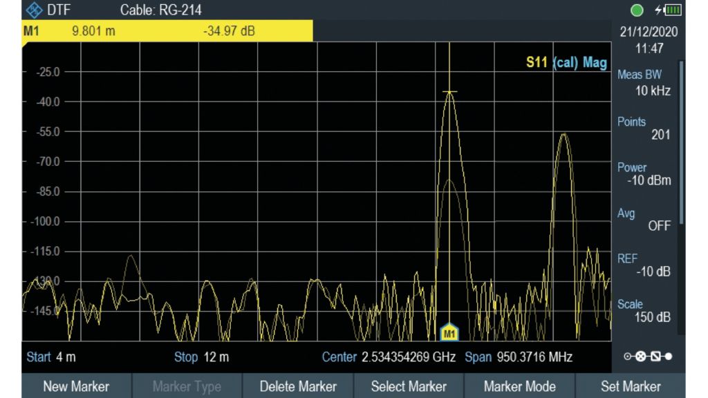
Fig. 1: Detecting fault with DTF measurement.
Open Lightbox

Application

Verifying the transmission path
Faulty cables, loose connectors or a broken filter in the transmission path can cause unwanted signal reflections. DTF measurements help to identify the exact location of the fault. For this purpose, the trace of a good cabling setup is saved as a calibrated reference DTF trace in the analyzer during installation.

By recalling setup and comparing the current DTF measurement with the stored trace, engineers can detect the abnormalities and identify the exact location of the fault. Fig. 1 shows a possible fault detected at a distance of 9.801 m from the test point, as indicated by marker M1.

Fig. 2: S21 insertion loss measurement.
Open Lightbox

Verifying rotary joint performance
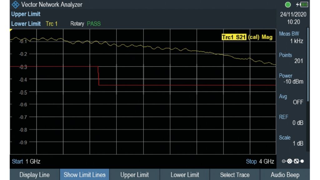
The network analyzer mode makes it possible to evaluate component performance degradation that violate the specification. Radar systems often use a rotary joint for the RF connection between the controller and the rotating antenna.

  • Verify performance of the rotary joint by evaluating the insertion loss variation over rotation
  • Perform a full two-port calibration to compensate the connecting cable loss
  • Connect the calibrated cables to the rotary joint input and output
  • Check the S21 measurements and alter them across all the rotating angles of the rotary joint to ensure the measurement is within the desired range

Fig. 2 shows an insertion loss measurement which has a maximum loss of 0.3 dB and is within the rotary joint specifications.

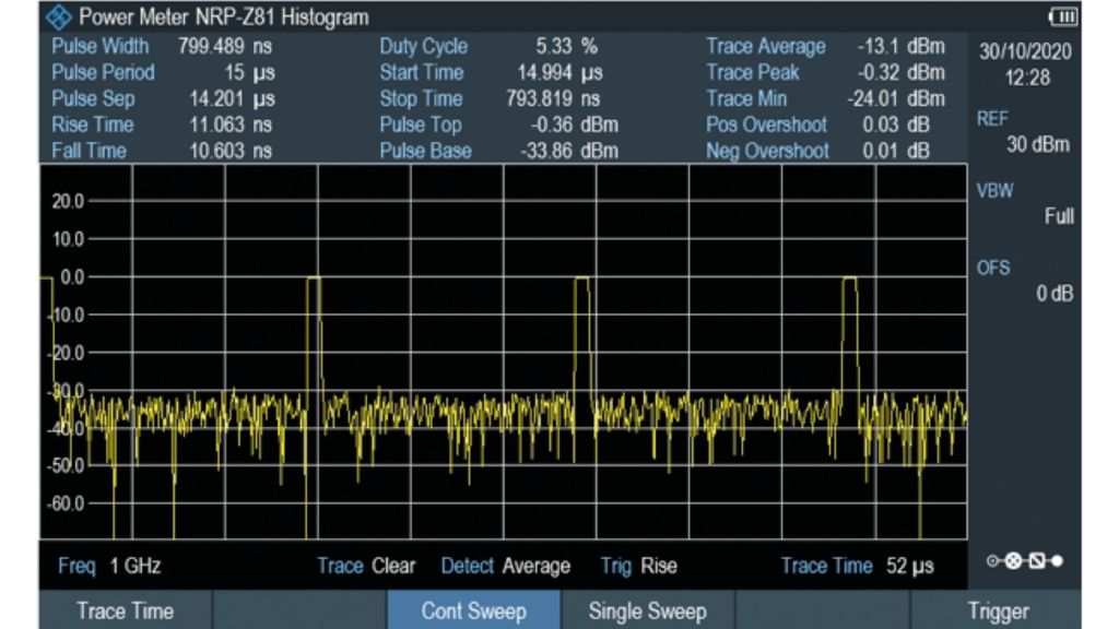
Fig. 3: Pulse measurement using peak power sensor.
Open Lightbox

Pulse measurement
Using the wideband power sensor in power meter mode allows engineers to verify the radar pulse characteristics. Peak power, pulse width, rise/fall times of the pulse and pulse repetition frequency of the transmit pulse are key parameters that are checked against the defined limits set by the international organizations. Connect the power sensor directly to the coupled transmitter output monitoring point for measurement. Any poorly shaped pulse will result in inaccuracy for the position and distance detected, causing incorrect target reading.

Summary

The robust R&S®ZNH is a perfect analysis tool, with many essential maintenance functions for at remote sites in a single unit. This means engineers can efficiently and quickly localize faults and reliably ensure system performance at remote sites.