Description
Possible reasons for the “Absorber Fail” warning of liquid-cooled THx9 transmitters.

Possible reasons for the “Absorber Fail” warning of liquid-cooled THx9 transmitters.
General:
The liquid-cooled transmitters of the THx9 series are high-power transmitters. Each transmitter rack can be equipped with up to 12 power amplifiers. Up to 6 transmitter racks can be combined with internal and external combining units to achieve the designated output power.
Transmitters with up to 8 amplifiers in a rack:
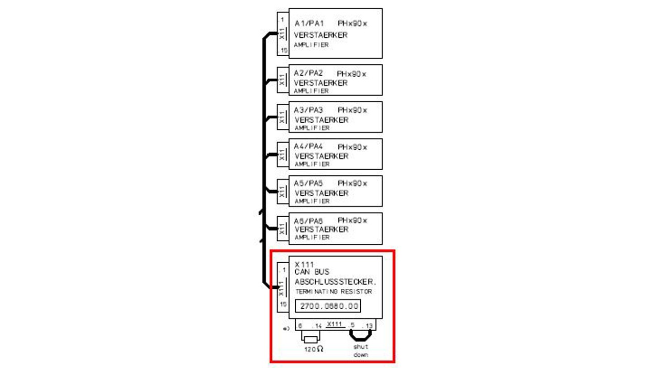
These transmitters have no external combining units. The absorber resistors of the internal combiners, are mounted directly on the liquid distributors and cooled by the liquid flow. The control cable which is routing the “Absorber Fail” to the “Shut Down” input of the power amplifiers, is therefore terminated with a link inside CAN BUS termination plug X111 (see attached drawing). In case of a “Absorber Fail” warning please check if this plug is missing.


Transmitters with 10/12 amplifiers in a rack and MultiRack transmitters:
The combining units are usually consisting of 2 Input Ports. One output port for the combined power and one port for the balanced absorber. Under normal operating conditions, both inputs are aligned in terms of level (power) and phase. The full power is routed to the coupler output. In case of unbalanced input conditions (level difference or phase difference) there is a power loss in the coupling unit. A part of the power will be routed to an absorber resistor. The absorbers in transmitter racks with 10/12 amplifiers and all absorbers of the rack combining units are equipped with a temperature sensor. Each sensor has a thermal contact, which opens a loop in case of exceeding a specific temperature to avoid that the related resistors in the absorber are overloaded. The open loop is connected to the shut-down inputs of the related amplifiers and disables the RF carrier. In case of transmitters with more than 2 racks an additional absorber loop board is used to route the signal lines of the absorbers to the related amplifiers.
The failure status is indicated with a “Absorber Fail” warning. It remains active, until the related absorber temperature has dropped below the trigger temperature of the thermal sensor. In this case the loop is closed again and the RF carrier in the related power amplifiers is enabled again. The “Absorber Fail” warning disappears.
In transmitter systems with a 208 V mains input an additional transformer is used to supply the transmitter control unit, the exciters, additional units and the cooling (pumps / fans) with a nominal voltage of 220…240 V AC. In this case, the mains input is equipped with an additional phase monitor in the power distribution. This phase monitor is used to monitor the 3 phases of the mains input. If one or more phases are missing or the mains input voltage is outside a specific voltage range, a built in relay contact opens. This contact is also connected to the shut-down inputs of the power amplifiers.
Conclusion:
The warning “Absorber Fail” can have 3 possible reasons:
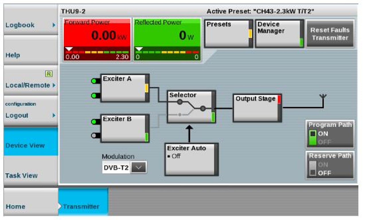
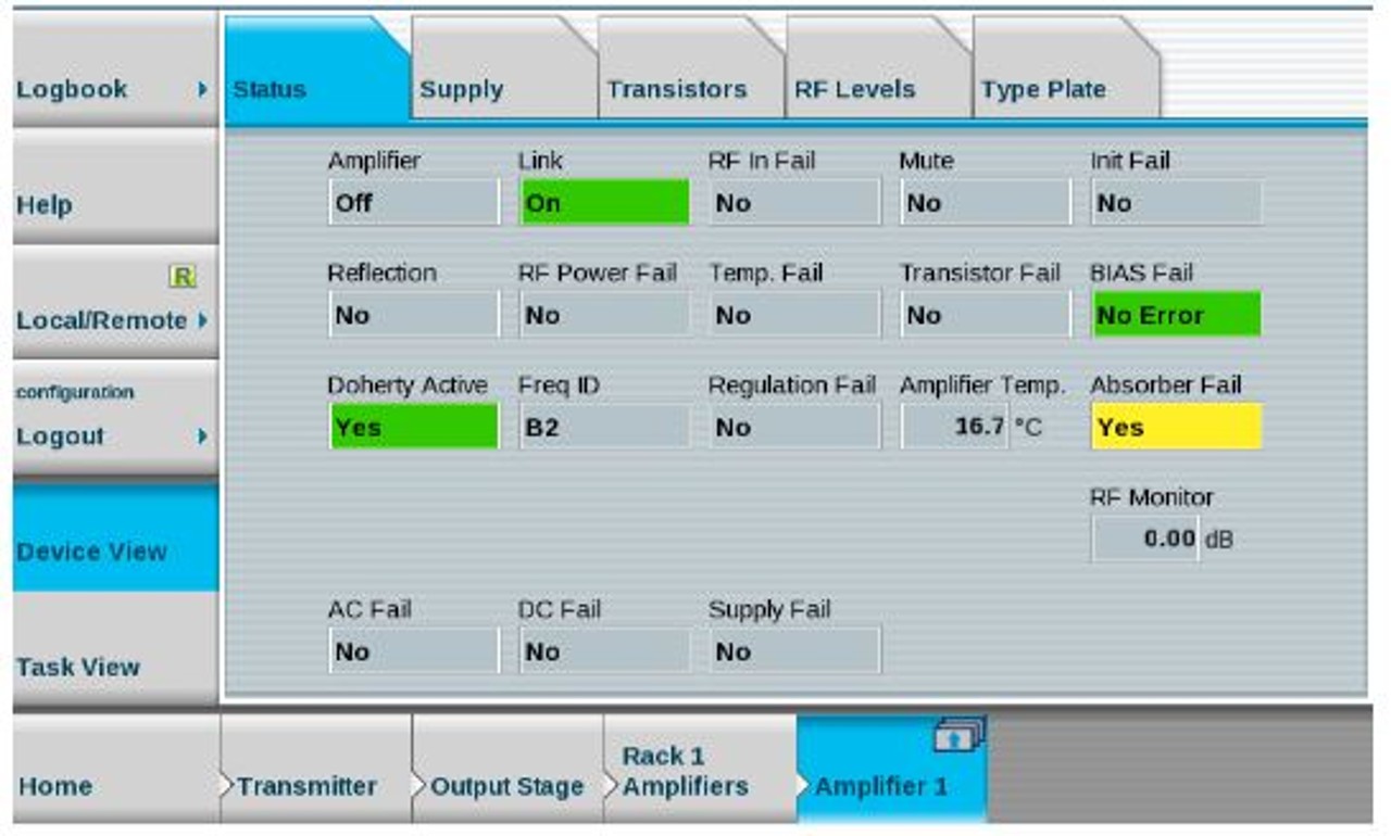
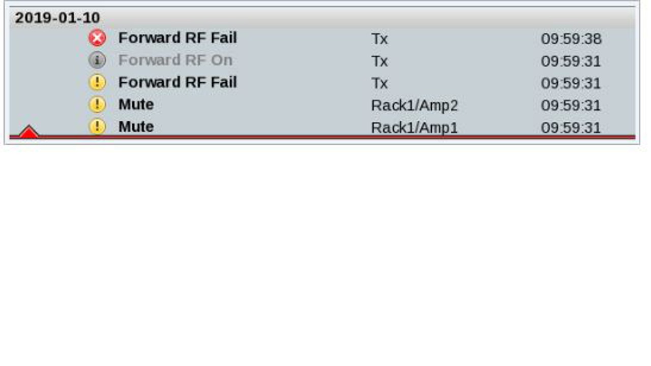
Typical fault indication in case of “Absorber Fail”
in transmitter device view


in amplifiers status


in logbook

