Test and measurement

Wideband spectrum measurements for synthetic aperture radar

Synthetic aperture radar (SAR) uses radar wavelengths for airborne or spaceborne ground mapping. The resolution of the SAR ground map depends on the range and cross-range SAR processing resolution. Cross-range resolution is determined by integrating pulses along a flight path for a period of time to create a synthetic aperture. Longer synthetic apertures result in finer cross-range resolution. Range resolution is achieved by radar waveform bandwidth in the form of a linear frequency modulated (LFM) chirp. Wider bandwidth enables finer range resolution.

Typical strip-map SAR scene created by an aircraft flying at a constant heading, velocity, altitude and range to the ground scene being mapped.
Open Lightbox

Geometry of a strip-map SAR measurement

The aperture depends on the aircraft velocity (v) and the SAR integration time (tint). After pulses are integrated for the time tint, the SAR creates the map for the current scene while integrating pulses for the subsequent scene along the flight path.

SAR resolution equations

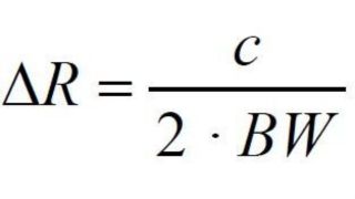
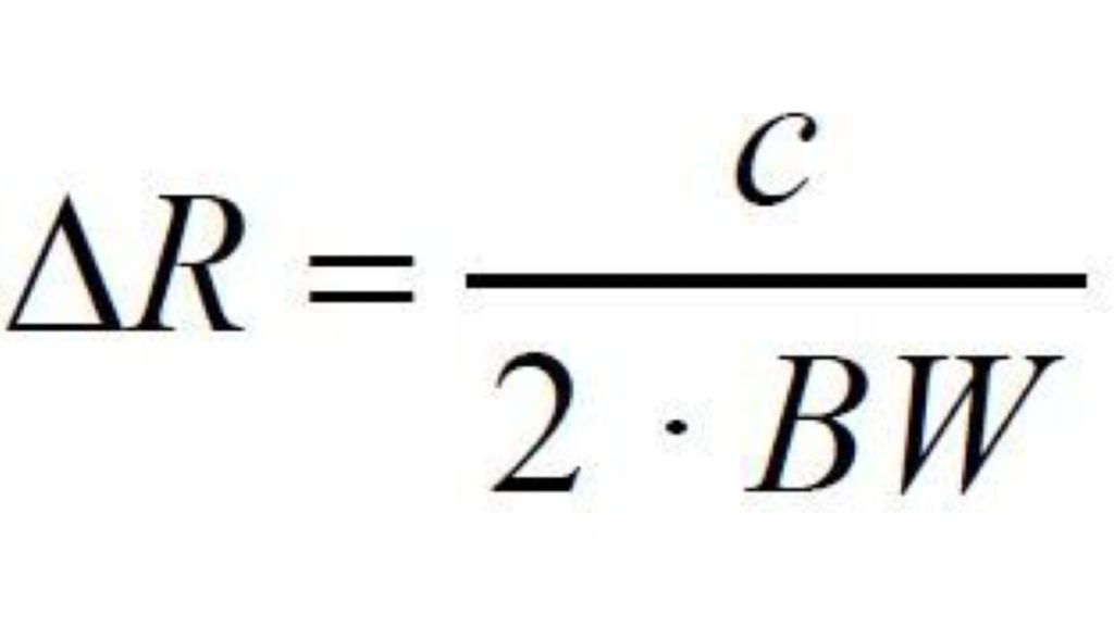
Range resolution (ΔR) is calculated with the equation:

Wideband-spectrum-measurements-for-synthetic-aperture-radar_ac_3608-9753_01_v6.jpg

With c as the speed of light, and BW as the LFM chirp bandwidth used in the SAR waveform. Greater LFM bandwidth results in finer range resolution. Sub-meter range resolution is often required.

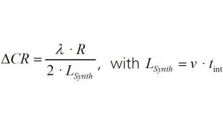
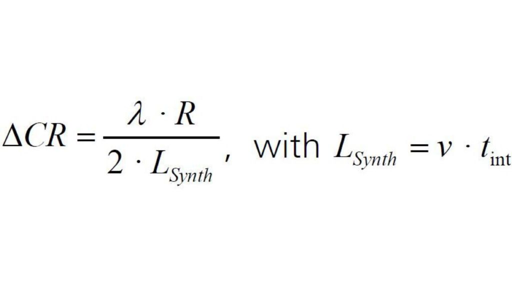
Cross-range resolution (ΔCR) is provided by the equation:

Wideband-spectrum-measurements-for-synthetic-aperture-radar_ac_3608-9753_02.jpg

With λ is the radar wavelength, R is the range to the scene, and LSynth as the length of the synthetic aperture or aircraft velocity (v) times the integration time (tint).

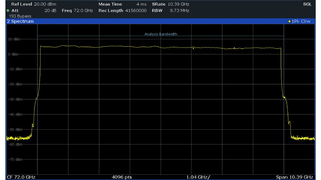
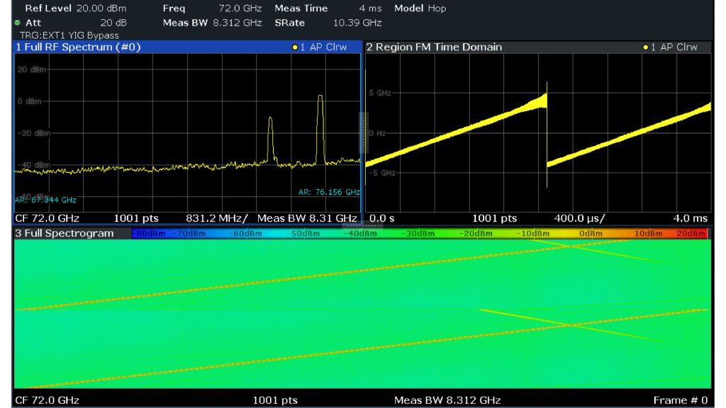
An 8 GHz LFM chirp measured on an R&S®FSW signal and spectrum analyzer with the R&S®FSW-B8001 8.3 GHz analysis bandwith option. 8 GHz chirp bandwidth provides approximately 2 cm SAR range resolution.
Open Lightbox

SAR systems dedicated to applications and bands

SAR is applied to the UHF band through to the X band, W band and beyond. The SAR wavelength depends on the application. The X band is typically used for high-resolution SAR imaging of urban terrain, ice and snow. Atmospheric absorption is tolerable at X band while it is intolerable in the K band due to water absorption. Bands such as UHF and S bands are good for measuring biomass and vegetation. The L band has good foliage penetration for geophysical measurements of ancient cities or rock formations beneath forest canopy [1]. Exciting new applications in 94 GHz, 140 GHz, 220 GHz and 235 GHz millimeterwave bands such as video synthetic aperture radars for aircraft landing in degraded visual environments. These SARs operate with wider waveform bandwidths for higher resolution.

One-dimensional active electronically scanned array
Open Lightbox

Newer SARs and all radar applications increasingly use active electronically scanned arrays (AESA). An AESA is usually a two-dimensional array of transmit/receive modules (TRM). Each TRM includes a circulator, a power amplifier, a phase shifter and a switch. A digital beamformer electronically controls the TRMs and tells the individual TRMs or TRM sub arrays the applicable amplitude and phase. The beamformer also applies aperture-tapering functions such as a Hanning window to reduce beamwidth and sidelobes. A receiver/exciter derived from a stable phase reference feeds the array. Radar returns can be phase-compared with a reference to measure Doppler shift.

TRMs are being developed for all the millimeterwave bands discussed above in a variety of materials such as indium phosphide (InP), gallium nitride (GaN), silicon germanium (SiGe) and silicon.

Typical setup for OTA testing of an SAR using an R&S®FSW: Antenna test chamber
Open Lightbox

Rohde & Schwarz solution

System-level radar tests are increasingly performed over the air (OTA) because it is easier than probing TRMs with a network analyzer and the close integration between the AESA and the radar receiver/exciter. A typical OTA testing setup is shown below with a radar in an antenna test chamber. The measurement equipment is a standard gain horn antenna connected to an R&S®FSW signal and spectrum analyzer.

The R&S®FSW signal and spectrum analyzer has the widest built-in analysis bandwidth for SAR measurements through most of the W band, enabling swept spectrum measurements with true preselection, image rejection and scalable vector signal analysis, pulse analysis, and transient analysis with 4.4 GHz bandwidth from 12 GHz to 18 GHz and 6.4 GHz or 8.3 GHz bandwidth above 18 GHz.

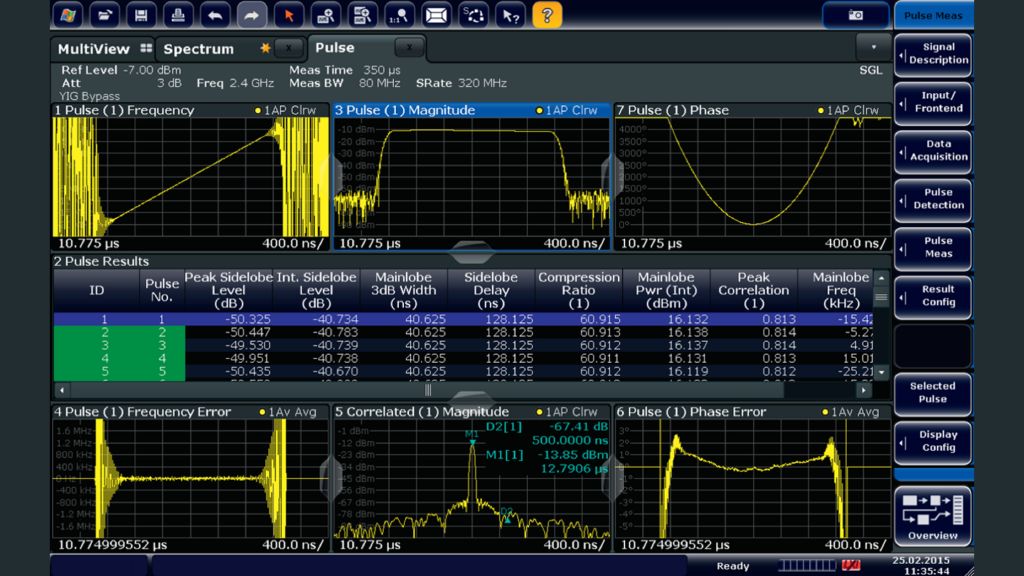
Time sidelobe analysis of pulsed LFM waveforms with the R&S®FSW-K6S option within the R&S®FSW-K6 pulse measurement application.
Open Lightbox

Use the R&S®FSW-K6 pulse measurement application to measure amplitude, pulse width, pulse repetition interval (PRI), frequency and phase for pulsed radar measurements. The statistics for these measurements can reveal pulse-to-pulse instabilities as discussed in the radar handbook by Mr. Skolnik [2]. Pulse-to-pulse phase instability from phase noise is discussed in the Rohde & Schwarz “Pulsed phase noise measurements“ application note [3].

In addition to pulse-to-pulse statistics, the R&S®FSW-K6S time sidelobe measurement option is available within R&S®FSW-K6 to measure phase nonlinearities within a radar pulse, exposing problems in the array or further upstream in the D/A converter (DAC). Nonlinearities in linear frequency modulated (LFM) chirps could originate from integral nonlinearity (INL) in the DAC or from AM to PM conversion in the power amplifiers or PIN switches in the TRMs. The Rohde & Schwarz application card “Time sidelobe measurements optimize radar system performance” (PD 3607.2626.92) [4] explains this phenomenon.

Finally, the R&S®FSW-K60 transient analysis application as explained in the Rohde & Schwarz application note "Automated Measurements of 77 GHz FMCW radar signals” [5] can be used to analyze wideband FMCW waveforms for SAR.

Summary

The R&S®FSW signal and spectrum analyzer facilitates swept spectrum analysis of next generation SARs with true preselection and image rejection up to 85 GHz and with no preselection up to 90 GHz. Use the scalable bandwidth options with a bandwidth of 4.4 GHz from 12 GHz to 18 GHz and a bandwidth of 6.4 GHz or 8.3 GHz above 18 GHz. Built-in measurement applications make statistical and waveform analyses of wideband, high-resolution SAR waveforms.

Analysis of an 8 GHz LFMCW waveform using the R&S®FSW-K60 transient analysis application.
Open Lightbox

References

[1] Article by Kelsey Herndon, Franz Meyer, Africa Flores, Emil Cherrington and Leah Kucera in collaboration with the Earth Science Data Systems. Graphics by Leah Kucera. Published April 16, 2020. “What is Synthetic Aperture Radar?”. NASA Earthdata. Retrieved 15 November 2020 from earthdata.nasa.gov/learn/what-is-sar

[2] Skolnik, Merrill I (22 January 2008). “Radar Handbook” – 3rd revised edition. New York: McGraw Hill

[3] Gheen, Kay (11 May 2016). Application note 1EF94 “Pulsed phase noise measurements“. Rohde & Schwarz. www.rohde-schwarz.com/appnote/1EF94

[4] Application card “Time sidelobe measurements optimize radar system performance” (PD 3607.2626.92, December 2020). Rohde & Schwarz. www.rohde-schwarz.com/applications/time-sidelobe-measurementsoptimize-radar-system-performance-application-card_56279-134857.html

[5] Dr. Heuel, Steffen (05 May 2014). Application note 1EF88 “Automated Measurements of 77 GHz FMCW Radar Signals”. Rohde & Schwarz. https://www.rohde-schwarz.com/applications/automated-measurements-of-77-ghz-fmcw-radar-signals-application-note_56280-59841.html

Related solutions