Ethernet testing solutions

Ethernet testing

Ethernet testing and data transmission technologies

Ethernet for computer networking was first introduced commercially in 1980, and adopted and standardized as IEEE 802.3 in 1983. By the end of the 1980’s Ethernet was the dominant local area network technology. The original much bulkier cable was superseded by the current cable with four twisted pairs of wires supporting 10BASE-T2 (using 2 of the twisted pairs) in 1990.
Maximum Ethernet data rates have increased from originally 2.94 Mbit/s now up to 400 Gbit/s. Currently, in data rate terms, the slowest link in the chain from device to device in many LAN is the copper twisted-pair cables, the basic cabling itself. The vast majority of installed cabling is Category 5/5e and Category 6 which supports 1GBASE-T with a maximum data rate of 1 Gbps (10 and 100 Gbps data rates require fiber-optic cables). 2.5GBASE-T and 5.0GBASE-T make it possible to increase the data rates to 2.5 Gbps, respectively 5 Gbps, on the existing cables for distances up to 100 meters.

Ethernet technologies have subsequently been adopted for other applications. Transmissions using single twisted pair cables, designated by “T1“ as in xBASE-T1, has turned Ethernet from incompatible with the motor car environment to a technology of choice for higher data rate signals in vehicles. Initially developed by Broadcom and marketed as BroadR-Reach, then promoted since 2011 By the OPEN Alliance (One-Pair Ether-Net) special interest group, the technology has been adopted as part of the 802.3 family of Ethernet standards, 100BASE-T1S as 802.3bw. The “S” is for short distance, under 15 meters, adequate for motor cars (40 meters is also supported). The physical layer is optimized for a single twisted pair of unshielded cables to significantly reduce wiring costs and weight, while retaining an acceptable level of EMC performance.

Automotive ethernet compliance testing

While xBASE-T1S has enabled Ethernet for motor cars, 10BASE-T1L (long distance; a range of up to 1000 meters) is the doorway for seamless Ethernet connectivity to the field-level devices (sensors and actuators) essential for automating manufacturing and processing installations; industrial Ethernet. 10BASE-T1L solves the challenges that, previously limited the use of Ethernet for process automation. These challenges include power, bandwidth, cabling, distance, data islands, and safe connections to hazardous areas applications. 10BASE-T1L can re-use the single twisted pair cables installed originally for technologies such as 4ma-to20mA, Highway Addressable RemoteTransducer, (HART) and Control and Communication (CC)-Links.

Your Ethernet test challenge

  • You need to test equipment conforming to everything from 10BASE-T to 10GBASE-T with the minimum of ethernet test equipment. For the higher data rate versions (2.5GBASE-T and faster) you need the best possible accuracy for transmitter linearity and return loss measurements.
  • You need a simple, quick, reliable, and accurate connection to 8P8C plugs, cables, and test points and tracks on a PCB, for the full range of Ethernet standards.
  • Compliance testing consists of a series of procedures that must be strictly adhered to, if the results are to be valid. You need to be sure you are conducting compliance tests correctly.

Our Ethernet test solutions

Rohde and Schwarz oscilloscopes support ethernet standards for data transmission for all three application areas:

  • Computer Networks
    Compliance test for 10BASE-T, 100BASE-T, 1000BASE-T, 2.5G BASE-T, 5G BASE-T, 10GBASE-T:
    Also for IEEE 802.3az, the energy saving supplementary standard for 100BASE-T and 1000BASE-T.
    Trigger and decode for 10BASE-T, 100BASE-T, MDIO.
  • Automotive
    Compliance test for 10BASE-T1S, 100BASE-T1S, 1000BASE-T1S, 2.5GBASE-T1, 5GBASE-T1, 10GBASE-T1.
    Trigger and decode functions for 100Base-T1, 1000BASE T1.
  • Factory/Industrial
    Compliance test to 10BASE-T1L, Ethernet-APL.

With high accuracy and a low noise floor, both R&S®RTO64 and R&S®RTP oscilloscopes support a wide range of Ethernet test requirements and standards for all three application areas supported by the individual options. In addition, for debug & verification the oscilloscopes offer extensive signal analysis tools such as fast statistical measurements, real-time eye, advanced jitter decomposition, and more. Options for an arbitrary waveform generator and a frequency converter reduce the need for additional test equipment to fulfill all compliance test requirements.

As well as oscilloscopes, R&S supply the complete set of equipment required for compliance test:

  • To simplify and automate compliance procedures using oscilloscopes with any Ethernet compliance option, the R&S®ScopeSuite provides:
    • The comprehensive Graphical Wizard to guide through the compliance procedures from beginning to end.
    • Automated control of all necessary oscilloscope settings and compliance test sequences.
    • Configurable test reports to document the test results.
  • Test fixtures for connecting industry-standard interfaces to the oscilloscope:
    • For computer LAN, 8P8C modular (RJ45) sockets meet requirements to test all established Ethernet specifications
    • For Ethernet-APL and 10BASE-T1L compliance test for factory applications, industry-standard ruggedized connectors and SMA connectors for a quick connect/disconnect to soldered cables.
    • A wide range of differential probes for attaching directly to test points on a PCB.
    • For return loss and conversion loss measurements, required by some standards for compliance testing, R&S®ZNB and R&S®ZND vector network analyzers.
    • For transmitter linearity measurements, required by some standards for compliance testing, Rohde & Schwarz spectrum analyzers, such as an R&S®FPC Spectrum analyzer
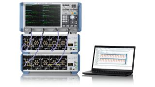
    • For compliance test on cable bundles using IEEE 802.3 for high speed Ethernet links for data transfer over a few meters; automate the test procedure to dramatically reduce test times, and increase test reliability with a setup including an R&S®ZNA or R&S®ZNB vector network analyzers for measurements, the R&S®OSP switch and control platform for multiport switching, and R&S®ZNrun to automate the process.
    • Run signal integrity measurements on backplanes, cables, and connectors, with R&S®ZNA and R&S®ZNB vector network analyzers. For both analyzer families, option K2 plus K20 provide time domain analysis including eye diagrams and simultaneous frequency domain analysis.

Benefits of our Ethernet solution

  • Minimize the equipment requirements and simplify test setups with oscilloscope options for an arbitrary waveform generator and frequency converter, so that a separate signal generator is not required.
  • Industry-standard sockets and connecters supported for computing, automotive, and factory/industrial applications.
  • Rigorously implemented compliance test in line with the appropriate IEEE 802.3 standard.
    For Ethernet there is no authority approving test cases as conforming to the standard. Be confident that a device tested with Rohde & Schwarz Ethernet compliance test equipment and approved as compliant will operate correctly with other equipment approved using Rohde & Schwarz Ethernet compliance test equipment. As well as accurate results, all compliance options feature fully illustrated step-by-step instructions from connecting the oscilloscope, the probes, the test fixture and the device under test, through to the end of the test sequence, including running individual tests, changing parameters in mid test, and setting user-defined limits.
  • Locate the data of interest with confidence.
    Fast hardware-based triggering across the complete signal bandwidth, including on data and control characters, control codes, and errors. Decoded data is displayed directly with the signal or in table format. Search on a wide range of data parameters and mark occurrences on both the signal display or in the decoded data table.
  • Both quick and intuitive and long-duration signal integrity testing.
    With the Data Eye analysis tools, investigate any problems with a signal. With a mask test set in the Eye, check the compliance over an extended period, to be certain that the signal is consistently compliant.

If you have any further questions regarding Ethernet testing, please contact us.

Related contents for Ethernet testing

An overview on Ethernet testing

This webinar is created for engineers who work on Ethernet design and test.
It starts with an introduction on the purpose and the different standards and applications of this digital interface. Challenges, specifications and test procedures open the webinar’s test and measurement core.

More information

Automated compliance test solution for high speed Ethernet cables

Testing High-Speed Ethernet cables according to IEEE 802.3bj, by, cd and ck requires the measurement of IL and RL on the high-speed data lanes as well as numerous NEXT and FEXT measurements and the calculation of the COM and ERL values. R&S©ZNrun-K410 and R&S©ZNrun-K411 provide full test automation and a comprehensive test report.

More information

Method of implementation (MOI) for IEEE up to 100 Gbps interface channel test

This application note describes Methods of Implementations (MOI) for precise, fast and error-free compliance testing of high-speed backplanes and direct attach copper cables (DAC) according to IEEE 802.3bj, IEEE 802.3by, IEEE 802.3cd and IEEE 802.3ck, based on 25 Gb/s, 50 Gb/s and 100 Gb/s signaling per lane with vector network analyzers from Rohde & Schwarz.

More information

Method of implementation (MOI) for IBTA 25+ Gbps serial interface cable testing

This application note describes Methods of Implementations (MOI) for precise, fast and error-free compliance testing of high-speed backplanes and direct attach copper cables (DAC) according to InfiniBand EDR and HDR specifications, based on 25 Gb/s and 50 Gb/s signaling per lane with vector network analyzers from Rohde & Schwarz.

More information

The importance of accurate S-parameters in PAM-4 applications

Accurate S-parameters are key when testing high-speed Ethernet backplanes and cables. They provide results such as return loss (RL), insertion loss (IL), near end/far end crosstalk (NEXT / FEXT) and are also the basis for calculating values such as channel operation margin (COM) and effective return loss (ERL).

More information

Knowledge+

Experience the uniquely personalized, high-quality content from the whole Rohde & Schwarz ecosystem - all in a single place. Discover now our knowledge tailored for your needs.

Video center

Get access to interesting videos and webinars about solutions, applications and products.

More information

Download Center

Search the Rohde & Schwarz download center for brochures, datasheets, technical papers, manuals, firmware, software, drivers, and more.

More information

The Rohde & Schwarz Technology Academy

You’re in great hands
Practical knowledge. Industry insight. Real experts. Only with the Rohde & Schwarz Technology Academy.

More information

Frequently asked questions (FAQs)

What does hdmi with ethernet mean?

High-Definition Multimedia Interface (HDMI) is a standard for transmitting audio/video data from the data source to the display/audio device to be viewed/listened to (a screen, a loudspeaker), at very high speeds, via a cable. The first version of HDMI was released in 2002; from 2010 with Release 1.4a onwards, HDMI can also transmit the ethernet signals used to connect computer devices in a network, via a cable. If a device is HEC (HDMI Ethernet Channel) compatible, connect the device to a source of the network data, using the HDMI cable. The core idea behind HEC was to simplify using a TV as the hub for a home network with an ethernet connection to internet, then use HDMI cables to provide all other connected devices high speed access to the internet, as an alternative to WiFi.

How do ethernet testers work?

Ethernet standards define test procedures to show conformance to requirements. While the test methods vary from standard to standard, what they have in common is testing signals output by the device under test to an oscilloscope. The oscilloscope measures the signal in comparison to the relevant test specification, for characteristics such as waveform jitter or distortion. A test fixture provides sockets for connecting the device to test and contact points for attaching probes. Software on the oscilloscope implements the test procedures and analyzes the results. Depending on the standard a signal source may be required. For some standards a network analyzer is also required to measure return loss. The oscilloscope requires a minimum bandwidth; depending on the purpose of the test and the Ethernet standard, ranging from a few hundred MHz to several GHz, and significantly higher accuracy and a lower noise floor than the DUT for reliable results.

Sign up for our newsletter

Stay up to date on upcoming trends and latest applications.

Sign up for our newsletter

Request information

Do you have questions or need additional information? Simply fill out this form and we will get right back to you.

Marketing permission

Your request has been sent successfully. We will contact you shortly.
An error is occurred, please try it again later.