Accurate verification of power supply startup sequences for auxiliary bias supplies

An offline AC/DC switching converter has no separate bias power supply that provides power to the control integrated circuit itself. Here, an auxiliary primary winding and discrete components are added to supply power to the control circuit. Verifying this circuitry is essential and requires accurate and detailed signal level and timing measurements. The startup sequence takes a long time, which needs to be taken into consideration in the measurement and requires an instrument with sufficient memory.

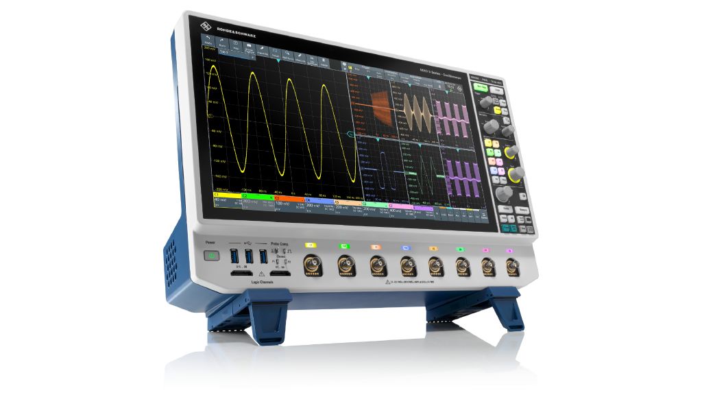
R&S®MXO 5 series oscilloscope
Open Lightbox

Your task

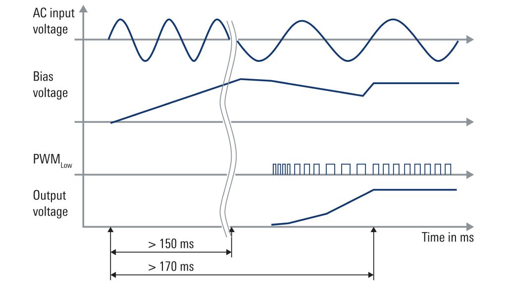
Bias power supply circuit designs for offline AC/DC power supplies are critical because of their impact on the power supply startup sequence. This sequence takes a relatively long time because bias capacitors are charged with very low constant current from the rectified pulsating DC voltage source. After the capacitors have been precharged and the bias supply exceeds the internal turn on threshold, a controller can start switching operations. An auxiliary winding supplies bias voltage after a few milliseconds. This auxiliary winding improves converter efficiency in normal operations. However, since bias capacitors supply only limited energy after constant current charging is completed, an under voltage event may occur before the switching operation can supply sufficient power through the auxiliary winding. Measuring input voltage, DC bias voltage, PWM signals and output voltage is vital when validating overlapping converter functions. Any anomalies such as incorrectly activated status signals must be detected in the long startup sequence when the current source is active. This is challenging and requires a high sampling rate and sufficient vertical resolution over hundreds of milliseconds.

Fig. 1: Typical startup sequence
Open Lightbox

Rohde & Schwarz solution

The R&S®MXO 5 series oscilloscope is ideal for this task because it can measure details at a high sampling rate with slow timebase settings thanks to the large standard memory of 400 Mpoints.

The 12 bit ADC vertical resolution provides greater detail of measured voltage levels when evaluating the turn on/ turn off thresholds for bias voltage. In combination with the highly sensitive digital trigger, distant trigger events can be captured to precisely catch a critical overlapping event when the regulator starts a switching operation after several hundred illiseconds.

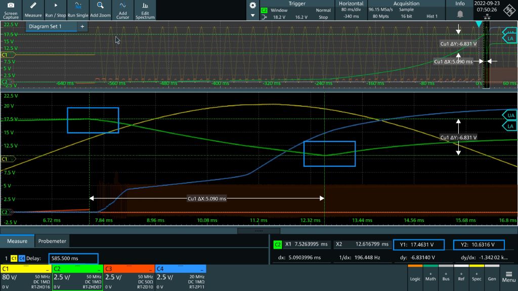
The zoom function can be used to view details from the high sampling rate of the PWM pulse. Fig. 1 shows a typical startup sequence.

Application

A 50 W offline AC/DC converter based on a flyback converter is used to measure the startup sequence of the output voltage specified as 20 V. This circuit provides an intelligent constant current function to optimize startup sequences. After completing the long constant current operation and exceeding the turn on threshold voltage of 16.7 V, the controller will run the internal softstart sequence. When the sequence is successfully completed, the converter will enter a steady state condition.

Device setup

Several tasks need to be completed before any startup:

  • A suitable channel setup must be in place and proper probes selected
  • A window trigger must be defined to capture the controller turn on event
  • Measurement functions such as a delay between input and output voltage must be activated
  • Various cursor settings must be selected to measure signal levels
  • A sufficiently high sampling rate of ≥ 100 Msample/s must be defined for high accuracy measurement of the PWM switching frequency (approx. 300 kHz) with sharp edges
  • A sufficient recording length must be set to catch the whole sequence
  • A suitable load must be defined for the converter during the startup measurement along with an AC power supply for the converter
Fig. 2: Startup sequence measurement of the converter
Open Lightbox

Measuring the startup sequence

After arranging the setup, the AC power source must be switched on to start the measurement. As soon as the trigger detects the minimum turn on threshold for the bias voltage, the waveforms will be displayed in the screenshot (see Fig. 2). The top window reveals the entire sequence and shows the delay between input and output voltage (channels 1 and 4). The duration here is 585 ms and the time the power supply needed before entering steady state operation can also be seen. More signal details can be seen with the zoom function. Moving the cursor over the image reveals the maximum turn on threshold for the bias voltage (channel 2) which is 17.4 V and the turn off voltage of 10.6 V. This level exceeds the critical data sheet value of 10.4 V, ensuring that the bias voltage supply from the auxiliary is fast enough.

Fig. 3: PWM details in steady state of the converter
Open Lightbox

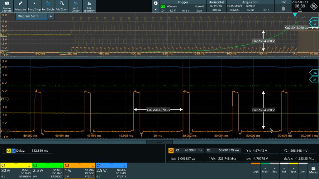
The PWM pulses (channel 3) illustrate how the controller works in detail. Another zoom window of the same measurement data highlights the PWM pulses in the converter steady state region (see Fig. 3). Moving the cursor over the area reveals the frequency for the steady state. The zoom can be adjusted for other important points in the sequence.

This complex measurement is only possible with the large memory of the R&S®MXO 5. Only 80 Mpoints of the 400 Mpoints of available memory were used. Longer startup sequences or higher sampling rates can also be verified.

Summary

The R&S®MXO 5 is ideal for verifying longer startup sequences where a highly detailed analysis is required for long recording times. The outstanding large standard memory in combination with 12 bit resolution can be used for a highly detailed analysis of critical startup sequences.