Maximizing power amplifier efficiency with harmonic load pull measurements
Harmonic load pull measurements explore potential device efficiency to find the best design topology.

Harmonic load pull measurements explore potential device efficiency to find the best design topology.
Load pull applications help improve power amplifier characterization and optimization. Efficient amplifiers are used in the non-linear region close to saturation where they produce a significant amount of harmonic power. To optimize power amplifier (PA) efficiency, these harmonic signals need impedance optimized for harmonic frequencies.


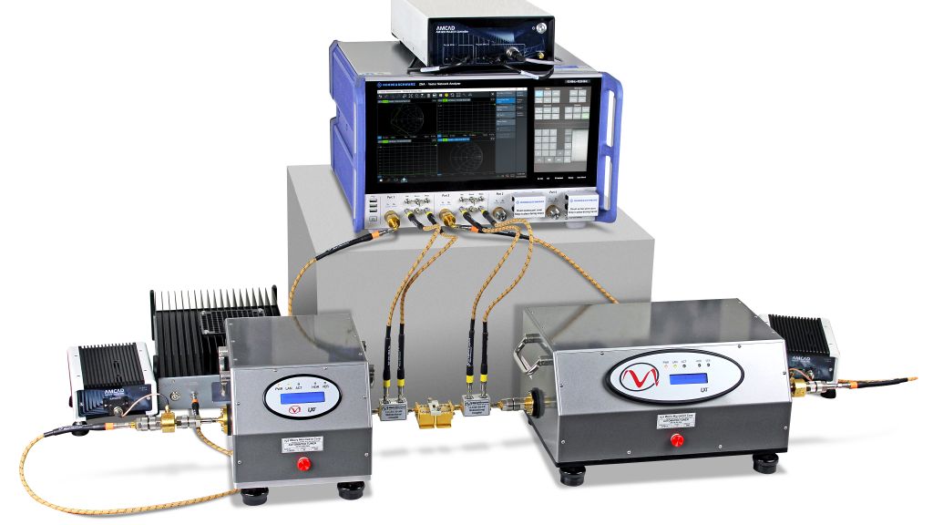
Load pull setup with the R&S®ZNA vector network analyzer at its core.
As a developer of RF power amplifiers, you focus on mandatory specifications such as gain, output power, frequency coverage along with sufficiently flat linearity, EVM and ACLR across the supported bandwidths. Significant effort is put into enhancing efficiency to differentiate from other suppliers on the market. When the amplifier is run close to saturation, it produces harmonic content. Different operating modes such as class A or class B are used to optimize between linearity and efficiency. These classes are called waveform engineering since the current and voltage curves applied on the transistor are tuned. While classes A and B are tuned by bias voltage, classes E and F use harmonic controls to optimize efficiency. A harmonic load pull system offers full insight into the E and F modes and can explore the most efficient operating modes for a DUT (amplifier). Efficiency enhancements in the 10 % to 20 % range are realistic, depending on the device and its operation modes.


Fig. 1: Basic passive vector receiver load pull setup
Traditionally, load pull systems use mechanical tuners in passive systems to apply different impedance levels to a transistor (see Fig. 1).
The active load pull system uses a different approach, where an active feedback system sends a signal to the amplifier output with a defined level and phase relative to the signal, replacing the tuner. The approach allows a wider tuning range across the Smith chart, since losses from the passive tuners are eliminated and more power is applied for a wider tuning range. A mixed approach (hybrid load pull) can also be used.


Fig. 2: Harmonic vector receiver load pull setup
When tuning harmonic frequencies, similar concepts are applied. Passive tuning uses multiplexed mechanical tuners for the first (f0), second (2f0) and third (3f0) harmonics.
They are combined via a triplexer or a cascaded mechanical tuner with three internal carriages for the harmonics. A wider tuning range and greater flexibility are available with an active system which provides controlled harmonic frequency signals to the DUT.
A common approach combines a passive tuner for the fundamental frequency signal, since they support much higher power levels, with active signals for the second and third harmonics (see Fig. 2).
Maury Microwave, AMCAD Engineering and Rohde & Schwarz have a joint turnkey system with software that can calibrate and run the entire system. The solution uses four independently adjustable yet synchronized signal sources unique to the R&S®ZNA, which can generate fundamental frequency signals for the input as well as second and third harmonics with phase and amplitude control for active harmonic load pulling (see Fig. 3).


Fig. 3: Active harmonic vector receiver load pull setup using R&S®ZNA sources
Alternatively, the fourth R&S®ZNA source can replace the mechanical tuner on the load side with an active f0 signal.
This is reasonable for devices with lower output power, as otherwise the signal at f0 driving into the output of the DUT would have to be excessive. A hybrid approach with a mechanical tuner plus an active signal to the DUT is the most flexible solution.
The R&S®ZNA has four internal sources for a very compact, fast and stable setup that saves the cost of external sources or harmonic tuners.
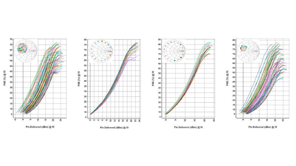
A measurement-aided approach characterizes the DUT using different conditions to search for an overall solution and generate the greatest efficiency. A multi-step approach that uses a system fully calibrated down to the DUT is common. The typical steps are (see Fig. 4):
Step 1: The f0 impedance is swept looking for the best PA efficiency while 2f0 and 3f0 are set to a 50 Ω termination.
Step 2: The 2f0 impedance is swept while the f0 is fixed to the impedance found in step 1 for the best efficiency. 3f0 remains at 50 Ω.
Step 3: The 3f0 impedance is swept while the f0 impedance and 2f0 impedance are fixed to the impedance found in steps 1 and 2 for the best efficiency.
Step 4: Fine tuning the f0 impedance: The f0 impedance is swept again while the 2f0 and 3f0 impedances are fixed to those found in steps 2 and 3 for the best efficiency.


Fig. 4: Efficiency curves along the optimization path
This scheme provides data to select impedance matching at the different harmonics for the best amplifier efficiency. Since these plots typically show efficiency over output power with multiple curves for different impedance levels, the P1dB or P3dB compression point can be selected as the optimal point for maximum output power or a point with better linearity can be selected by using a back-off greater than 3 dB.
Efficiency curves along the optimization path (Fig. 4)
The plots show power added efficiency (PAE) over the output power delivered at the output of the transistor. The range of impedance variation is also shown on the Smith chart for each step. The y-axis scaling changes to allow room for larger PAE values when the impedance is changed to achieve the best efficiency.
The joint solution from Maury Microwave, AMCAD Engineering and the R&S®ZNA from Rohde & Schwarz is a unique and compact approach to harmonic load pull measurements when developing the latest amplifiers.
Since advanced amplifier classes, such as classes F or J are commonly used in modern wireless communications systems, having the best efficiency and harmonic termination are important to keeping power consumption as lowas possible.