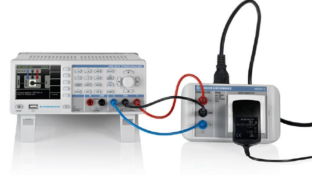
Measurement of conducted emission limits in line with IEC/EN 61000‑3‑2

Most of today's electronic devices draw non‑sinusoidal current. This gives rise to harmonic currents injected back into the public supply system. These need to be checked on all devices with the CE marking.

Your task

Modern electronic devices use switched‑mode power supplies that can generate strong harmonic currents which are injected back into the mains supply network. The limits for harmonic current emissions are defined in IEC/ EN 61000‑3‑2, divided into four equipment classes. Based on the class and cycle time, the harmonic currents must be analyzed over precisely defined time periods and comply with the specified limits.

To achieve the required accuracy up to the 40th harmonic, automated test cases are essential.

T&M solution

The R&S®HMC8015 power analyzer provides seamless acquisition and realtime signal processing and accelerates the measurement. Precise measurement ensures that compliance with the standard can be determined, even for critical designs.

The DUT is simply and safely plugged in to the R&S®HMC8015 through the optional R&S®HZC815 mains adapter. For this purpose, the cables supplied with the adapter are connected to the sockets on the front of the instrument. Various country-specific adapter models are available to enable connection in different countries.

Application

The setup wizard eliminates guesswork

The setup wizard in the R&S®HMC8015 guides the user through the measurement and configures the required instrument parameters. That minimizes measurement errors and makes results quickly visible. The measurement process is fully automatic. No prior knowledge of the abovementioned standards is necessary.

All environmental variables, such as the supply voltage and mains quality, are constantly monitored and displayed during the measurement. Deviations are color-coded.

The measurement steps - step 1

Select the IEC/EN 6100‑3‑2 standard in the wizard

Step 2

Set the correct mains voltage and mains frequency (manually, or automatically based on the selected region) and set the expected power consumption of the DUT.

Step 3

Select the right device class.

Step 4

Set the crest factor and maximum current (RMS).

Step 5

If known, set the current consumption pattern (static, cyclic or variable) in order to speed up the measurement.

Step 6

Connect the DUT as shown in the wizard and put the DUT in the desired operating mode.

Step 7

The results, including min. and max. values, are clearly displayed during and at the end of the measurement.

measurement-of-conducted-5216-2418_05.png

Test report

When the measurement is finished, the results can be saved to a USB flash drive. An interactive HTML form is created that can be filled in with customer data to adapt the test report to your specific needs.