R&S®Essentials | Digital oscilloscope fundamentals
Debugging serial protocols with an oscilloscope
Author: James Lewis l Test & Measurement expert and blogger
Get ready to dive into the fascinating world of UART, I2C, (Q)SPI and CAN bus. You'll not only learn about these serial protocols but also discover how to debug them using an oscilloscope. From practical tips to real-world insights, we've prepared the basics to help you master protocol debugging.
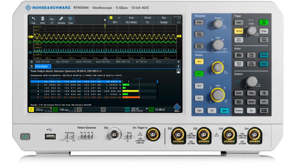
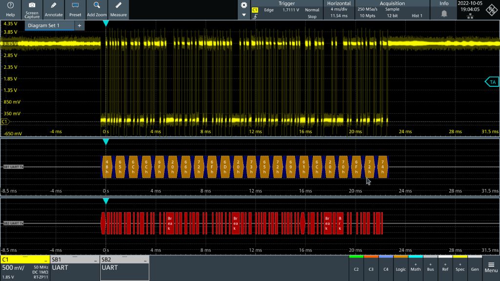
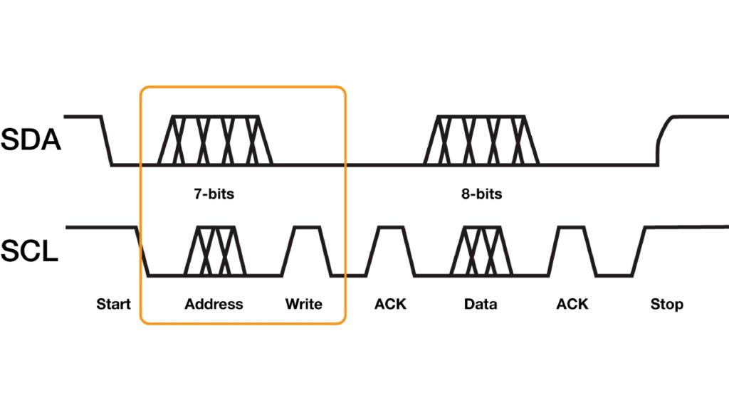
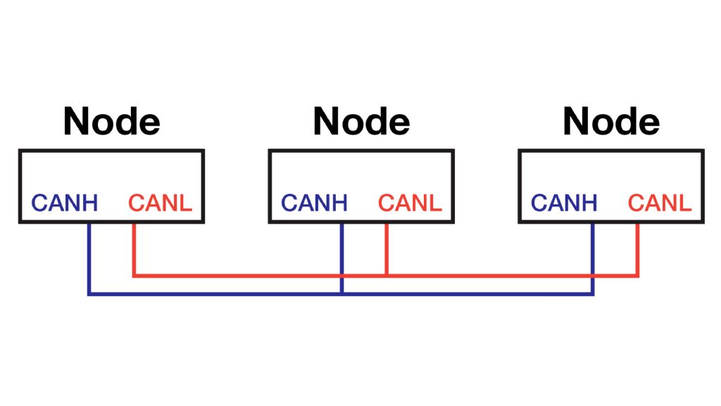
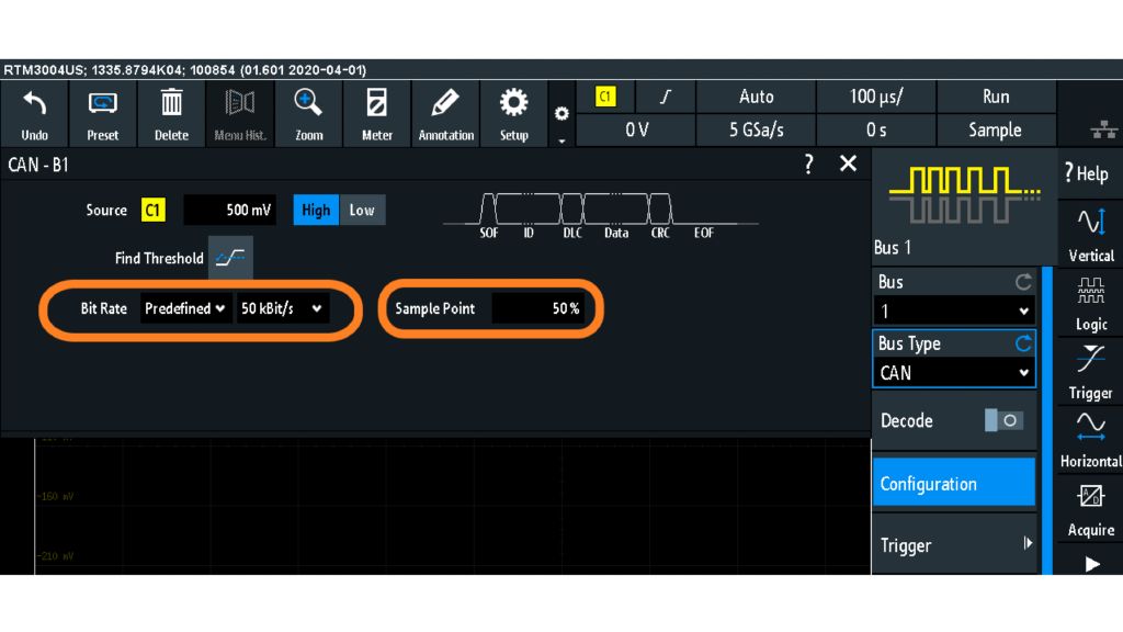
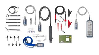
Edge computing devices can have a microcontroller (MCU) connected to sensors, actuators, buttons and displays. Most of these discrete devices communicate with the MCU using a digital protocol, such as UART, I2C or CAN. One advantage to debugging these serial protocols with an oscilloscope is that the small number of signals is easier to probe compared to the wide parallel buses of the past. With probes, oscilloscopes offer a deep set of analysis tools that would otherwise require a separate protocol analyzer. Here are some tips on how to use an oscilloscope to decode serial protocols and introductory information for the most common serial protocols.


