Application Notes

A customized transformer design needs a powerful LCR bridge

A high frequency transformer is a key component when designing isolated switching mode power supplies (SMPS). Leakage inductance is essential in the control of many design parameters including efficiency, maximum voltage rating for switching elements and EMI when it comes to designs using customized transformers. Accurate measurement of this parasitic element is mandatory. The R&S®LCX LCR meter is ideal for this challenging measurement task.

Your task

The impact of leakage inductance from SMPS transformers depends on several factors. Designing a transformer to obtain greater magnetizing inductance tends to increase leakage inductance, especially if isolation is required between the primary and secondary winding. This leakage inductance may cause power losses and influence EMI emissions especially at higher converter switching frequencies.

If the transformer is designed to operate in a flyback converter, the main converter switch will be sensitive to voltage kickback from leakage inductance when the driving transistor turns off. The energy stored in the leakage inductance requires snubber circuits to limit voltage in the switching devices. During the design process, an accurate measurement of leakage inductance on the primary transformer side is essential for an optimized snubber circuit design. This ensures sufficient protection for the main switching element but also reduced losses and fewer EMI problems.

Besides leakage inductance, other parameters such as magnetizing inductance, winding capacitance and winding resistance are relevant and needed for high-quality designs.

An accurate simulation model can also be derived from the measured parasitic transformer values to accelerate the design process.

Primary and leakage inductance measurement principle
Open Lightbox

Rohde & Schwarz solution

The R&S®LCX LCR meter can accurately measure all critical transformer parameters. Sinusoidal voltage with a suitable frequency is required for transformer inductance measurements. The required test frequency is derived from the converter switching frequency. The LCR meter provides the AC signal, while the secondary winding is in open-circuit configuration. The primary inductance LTotal can then be measured.

The measurement result combines the magnetizing inductance LM with the leakage inductance LL. Primary transformer inductance is determined by the core permeability and the number of turns in the winding. A series resistance element RS also results from the copper windings. This value can also be measured while applying an AC signal or also measured as pure DC. This value helps calculate copper losses.

Since leakage inductance is defined by the transformer design, it cannot be measured directly. A suitable method for leakage inductance must eliminate magnetizing inductance from primary inductance. This can be done with a short circuit across the secondary terminals. A short circuit results in zero volts on the output terminals and zero volts for the magnetizing inductance on the primary side. The measured inductance at the primary terminals is then the leakage inductance.

Application example

The customized transformer design for measuring the relevant parameters is placed in an offline power converter with an output voltage of 5 V at 2 A using the flyback principle.

Measurement tasks

  • Perform compensation (open/short measurement without the DUT connected)
    • To compensate for residual parameters such as cabling
  • Set the desired operating frequency and a suitable voltage test level
  • Select a proper impedance mode (lowZ or highZ)
    • To achieve the greatest accuracy
  • Choose a suitable range setting, select the correct parameter configuration (Ls and Rs/Ls and RDC), connect the DUT and start the measurement

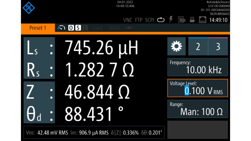
The screenshot below reveals a primary inductance of 745.3 µH which complies with data sheet specifications.

Primary inductance measurement at 10 kHz and 100 mV (RMS)

It also shows series resistance of 1.283 Ω. DC resistance is specified in a typical transformer data sheet and should be measured in DC. This can also be measured with the LCR meter by selecting the RDC parameter. The resulting DC resistance is about 1.41 Ω.

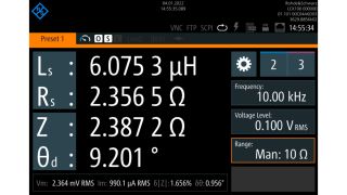
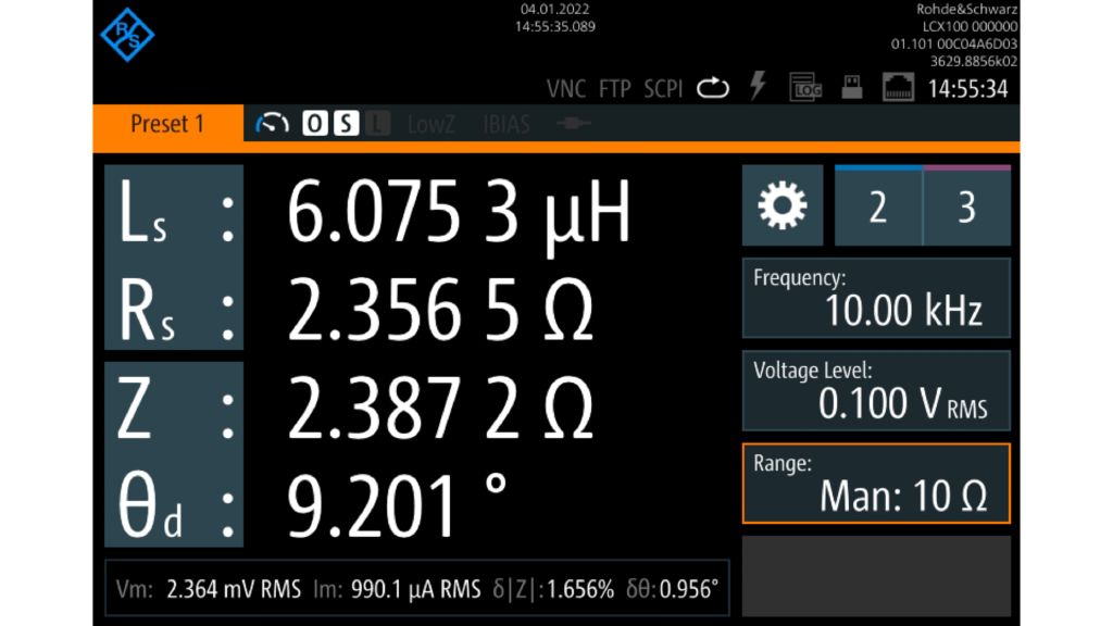
The screenshot below shows leakage inductance of about 6.08 µH, which is also within the data sheet specifications. After measuring leakage inductance, the magnetizing inductance can be calculated.

LM = LTotal − LL = 745.26 µH – 6.08 µH = 739.2 µH

Leakage inductance measurement at 10 kHz and 100 mV (RMS)

Summary

The R&S®LCX LCR meter combines powerful capabilities and high accuracy, making it a great instrument to support transformer designs in various switching converters. In most converter designs, leakage inductance must be controlled regardless whether leakage energy is dissipated in a snubber circuit or reused for zero voltage switching in resonant converters. Being able to measure various transformer parasitics enables designers to set up a very accurate simulation model. In a production line, a measurement of leakage inductance ensures quality in customized transformer designs for incoming inspections.

Designation Type Order No.
LCR meter, 300 kHz R&S®LCX100 3629.8856.02
LCR meter, 500 kHz R&S®LCX200 3629.8856.03
Kelvin clip lead R&S®LCX-Z2 3638.6446.02