Detecting infrequent anomalies in the spectrum of mixed signal power designs

In addition to the main function, power electronic circuits very often have to provide other essential functions such as interfacing with submodules to fulfill system design requirements. Power designs therefore include bus communications in combination with a microcontroller. This can easily lead to more complex designs that may have a negative impact on the conducted emission measurements. Sometimes these auxiliary functions generate emissions infrequently, making it challenging to locate and isolate the root cause. An instrument with a very fast FFT analysis capability is essential to find infrequent events efficiently.

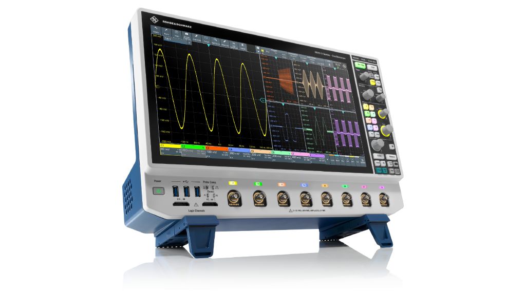
R&S®MXO 5 series oscilloscope
Open Lightbox

Your task

In power designs, e.g. motor drivers for brushed DC motors, analog and digital circuits coexist on the same printed circuit board. The designer has to consider this complexity, particularly in terms of the conducted emissions present on the power lines. Clocks of microcontroller or bus communications such as SPI may contribute to the emissions if the printed circuit board is not designed properly. Sometimes bus activities do not happen continuously; they are often initiated by other external system controllers. While measuring conducted emissions on the power lines, these bus activities often cause infrequent events in the frequency spectrum. Oscilloscopes are the standard instrument for debugging conducted emissions during the development process. However, for detecting very short and infrequent events in the spectrum, an oscilloscope with a standard FFT implementation has limitations. These are mainly due to the time-consuming calculation process before the FFT spectrum can be displayed. Rare, short, infrequent events could be missed while the FFT spectrum is being calculated. Much faster FFT performance is essential to locate and isolate the root cause.

Fig. 1: Debugging conducted emissions.
Open Lightbox

Rohde & Schwarz solution

The R&S®MXO 5 series oscilloscope is perfect for this challenging task because it measures the spectrum and provides fast, in-depth insights into conducted emissions. The fast FFT capability enables the user to acquire a spectrum with up to 45 000 FFT/s. In combination with the low-noise analog frontend, users can detect rare events very efficiently and accurately.

Furthermore, the FFT is independent of the time domain settings, which is highly beneficial for EMI debugging. In standard FFT implementation, the update rate of the FFT would be reduced significantly due to the resolution bandwidth. Additionally, near field probes can be used to locate the noise source in the system. This also requires a fast FFT. The artificial mains network (AMN) is required for stable and reproducible measurements.

Application

A fully integrated half-bridge driver including a connected brushed DC motor was used to show an infrequent event in the conducted emission spectrum. This device under test (see Fig. 1 on page 1) provides the power part with two half bridges and can be configured through an SPI bus. A microcontroller is connected to the bus and used to monitor the status of the driver and to control the speed and direction of the motor. A CAN bus is used to communicate to modules outside of the system.

Finding the root cause

The procedure can be divided into three steps:

  • Step 1: Perform the measurement of the conducted emissions in line with the required standard, e.g. CISPR25, with activated persistence mode (highlights any rarely occurring anomalies)
  • Step 2: Find and locate the root cause with suitable electrical and magnetic near field probes of different sizes (find emissions that correlate to a specific board functionality)
    Note: Persistence mode should still be activated to provide non-periodic insights
  • Step 3: After finding the correlation between spectrum and dedicated function, deactivate the infinite per-sistance mode; trigger on the signal that is highly likely to be the root cause (the mesaurement will confirm whether the assumption is correct or if step 2 has to be repeated)
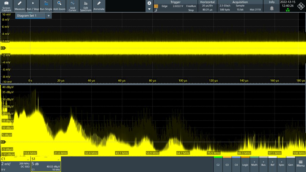
Fig. 2: Conducted emission measurement on the power lines.
Open Lightbox

Measurement example

The conducted emission measurement result on the power line of the brushed motor application is shown in Fig. 2. The fast FFT in combination with the activated persistence mode enables rare events to be detected that cause a high emission over the entire spectrum. This noise envelope (see light yellow area, indicated with white arrows) shows typical signatures that are caused by a broad noise source, e.g. bus communications or the clock. After the conducted emission measurement, the near field probe is used and it is possible to find emissions with similar characteristics on the printed circuit board close to the SPI data tracks next to the microcontroller. It can therefore be assumed that the SPI activity is probably the root cause.

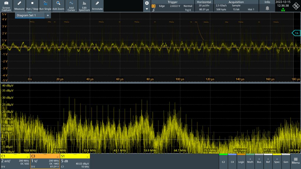
Fig. 3: EMI spectrum while SPI data is transmitted.
Open Lightbox

A confirmation can be obtained with the last step (see Fig. 3). In this measurement, the normal trigger mode is activated where the SPI communications port is measured with a passive probe (channel 3). The spectrum is displayed at the same time. The result shows that as soon as the SPI communications between the controller and receiver have started (trigger event), a high broad emission appears on the display. Knowing the details, activities can be defined to limit this emission, which is caused by SPI bus activities and reflected into the conducted emissions on the power line.

Summary

The R&S®MXO 5 series oscilloscope is perfect for verifying conducted emissions in mixed signal applications where infrequent emissions may occur. The outstanding fast FFT implementation of 45 000 FFT/s in combination with the low-noise analog frontend enables the user to find any rare anomalies in the frequency spectrum of mixed signal power designs.