Verifying 10BASE-T1S interfaces for automotive Ethernet

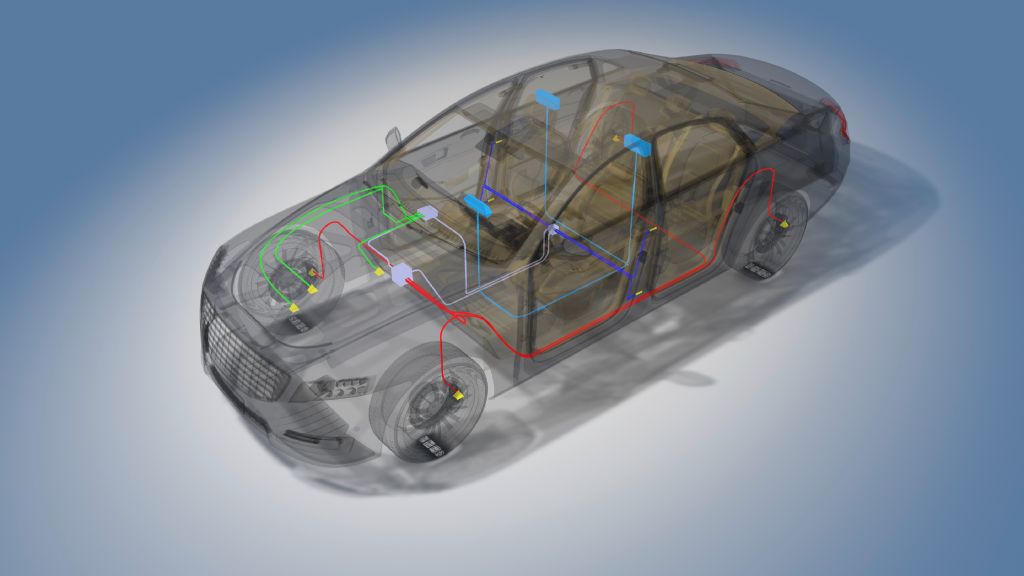
10BASE-T1S Ethernet enables the integration of diverse sensors into an automotive-Ethernet vehicle supply system, for example short-range radar sensors for detecting blind spots or ultrasonic sensors for the parking assistant. For reliable operation of the functions, data transmission over 10BASE‑T1S Ethernet must be assured at all times and in every climatic environment. Functionality must be tested during development and in production. Only 10BASE-T1S Ethernet interfaces that have passed compliance testing in line with IEEE 802.3cg can be deployed in vehicles. Consequently, vehicle manufacturers and their suppliers need measuring equipment that allows them to perform these tests quickly and reliably.

Verifying 10BASE-T1S interfaces for automotive Ethernet

Your task

10BASE-T1S Ethernet enables the integration of diverse sensors into an automotive-Ethernet vehicle supply system, for example short-range radar sensors for detecting blind spots or ultrasonic sensors for the parking assistant. For reliable operation of the functions, data transmission over 10BASE‑T1S Ethernet must be assured at all times and in every climatic environment. Functionality must be tested during development and in production. Only 10BASE-T1S Ethernet interfaces that have passed compliance testing in line with IEEE 802.3cg can be deployed in vehicles. Consequently, vehicle manufacturers and their suppliers need measuring equipment that allows them to perform these tests quickly and reliably.

Background

Automotive Ethernet with single twisted-pair network technology enables fast and cost-effective data communications in vehicles. It allows the integration of electronic control units (ECU), a wide variety of sensors, rear-view cameras and other devices into vehicle supply systems. The new IEEE 10BASE‑T1S standard makes it especially easy to integrate devices into automotive Ethernet using the multi-drop configuration. Unlike the star topology of 100BASE-T1, no additional switches are needed, and the cabling is simpler. Vehicle bus systems such as CAN or LIN can easily be replaced by 10BASE‑T1S. There is no need for gateways to connect different bus systems. 10BASE-T1S communicates in half-duplex mode over a twisted pair and enables data transmission at 10 Mbit/s. Data collisions due to simultaneous transmission by multiple devices are prevented by physical layer collision avoidance (PLCA). For interface verification, the IEEE 802.3cg standard specifies compliance testing with six test cases.

Rohde & Schwarz solution

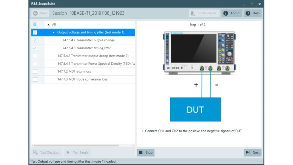
The excellent signal fidelity and test automation capability of the R&S®RTO and R&S®RTP oscilloscope families make them ideal for 10BASE‑T1S compliance testing. With the options for 10BASE-T1S Ethernet compliance tests (R&S®RTO-K89 and R&S®RTP-K89), measurements can be performed in line with the IEEE 802.3cg standard, either single-ended or differentially with a differential probe. A test fixture is available for connection to the 10BASE-T1S interface of the test setup. Along with the oscilloscope, complete compliance testing requires a vector network analyzer such as the R&S®ZND for MDI return loss and MDI mode conversion loss measurements. Control of the measuring instruments, calculation of the results and documentation can be automated with the R&S®ScopeSuite test software. A test wizard guides the user step by step through the test procedure with illustrated instructions (Fig. 1). This virtually eliminates incorrect measurements due to operator errors. R&S®ScopeSuite is a standalone application that can be installed in a separate PC or an R&S®RTO or R&S®RTP oscilloscope.

Fig. 1: A graphic wizard guides you through the test cases
Open Lightbox

Application

Ethernet compliance testing focuses on the quality of the transmitter. Compliance testing requires specific signals from the transmitter. Every communications chipset must be able to generate these signals on its own. The test signals are activated using a computer with test software from the manufacturer, for example through a USB interface. After a test has been selected, R&S®ScopeSuite first visualizes the test setup. Then – before starting the test – it displays the expected test signal for verification. This allows the signal measured by the oscilloscope to be checked for plausibility. The test setup and the configured test signal can be modified if necessary. Then the test is started and performed automatically. The compliance test runs very fast and delivers reliable and reproducible results.

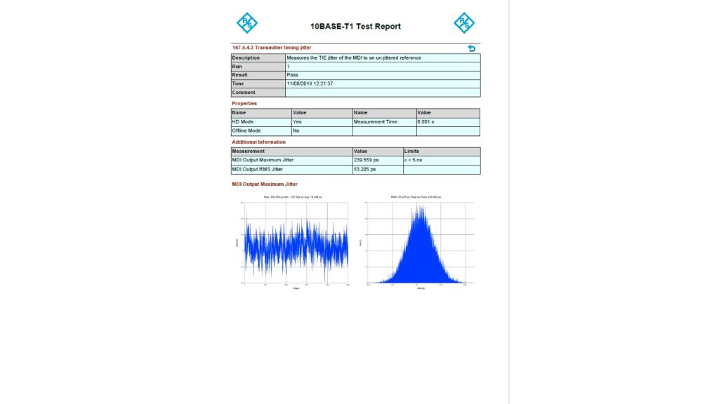
The limit editor can be used to change the test limits to meet different quality requirements for signal integrity testing during product development. The test record documents the test limits and all test results. The user can see at a glance whether all tests were passed.

Summary

The 10BASE-T1S Ethernet compliance test offers:

  • Test solution for 10BASE-T1S interface
  • Compliance test in line with IEEE 802.3cg
  • Predefined, automated test steps
  • Step-by-step wizard for user guidance
  • Clear and comprehensive test documentation
Fig. 2: Clear and comprehensive test report
Open Lightbox

Related solutions