
Your task
Faulty components can be identified quickly by analyzing their current-voltage characteristics. A component tester is especially convenient for this purpose. It facilitates quick testing of capacitors, resistors, transistors, thyristors, inductors, Zener diodes, other diodes, and circuits composed of these components, such as rectifiers. However, in many cases a component tester is not readily available.
T&M solution
The R&S®RTC1000 oscilloscopes provide a built-in component tester. It consists of a signal generator that applies a sine-wave signal at 50 Hz or 200 Hz with a defined amplitude (max. 9 V) and limited current (max. 10 mA) to the DUT. In this mode, the oscilloscopes use the A/D converter to digitize the signals influenced by the component and display them as a current versus voltage signal.
Operating principle
The operating principle can easily be illustrated using a linear passive component as an example. Fig. 1 shows the I/V characteristic of a 2.1 kΩ resistor connected to the component tester. The linear behavior of the component is clearly visible. The current rises linearly with increasing voltage. For example, the current is approximately 2 mA at a voltage of 4 V. According to Ohm’s law, the resistance value is approximately 2 kΩ.
The linear relationship between current and voltage with a real resistance can be checked using a second resistor. Fig. 2 shows the I/V characteristic of another component connected to the component tester. The steeper slope of the characteristic means that more current flows at the same voltage than with the 2.1 kΩ resistor. According to Ohm’s law, the resistance of the second component is lower. The current at 0.9 V is approximately 8 mA. The result is a resistance value of approximately 110 Ω. The component tester of the R&S®RTC1000 oscilloscopes can also display the characteristics of nonlinear passive components, such as capacitors. Fig. 3 shows a 0.1 μF capacitor connected to the tester and initially stimulated by a 50 Hz signal. The nonlinear characteristic can easily be recognized from the elliptical shape of the resulting curve.
The frequency dependence of the I/V characteristic can be illustrated by simply changing the stimulus frequency to 200 Hz. The capacitor reactance can be calculated using the following formula:
This means that with constant capacitance, the reactance drops with increasing frequency. The curve in Fig. 4 shows the result of stimulating the 0.1 μF capacitor with a 200 Hz signal. The distinctly smaller elliptical shape corresponds to the formula for calculating the capacitor reactance.
The component tester can additionally be used to display the quasi-static characteristics of active components, such as diodes. Under static conditions, a simple silicon diode starts conducting current in the forward direction at a voltage of about 0.4 V. Fig. 5 shows this typical behavior. The current rises very quickly above a voltage of approximately 0.5 V.
The current-voltage characteristics of complex components, such as Zener diodes, can also be displayed and analyzed easily with the component tester of the R&S®RTC1000 (see Fig. 6).


Fig. 1: I/V characteristic of a 2.1 kΩ resistor.

Fig. 2: I/V characteristic of a 110 Ω resistor.

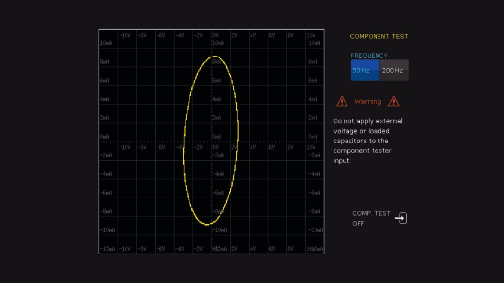
Fig. 3: I/V characteristic of a 0.1 μF capacitor at a 50 Hz stimulus signal.

Fig. 4: I/V characteristic of the same 0.1 μF capacitor as in Fig. 3, but at a 200 Hz stimulus signal.

Fig. 5: I/V characteristic of a silicon diode.

Fig. 6: Characteristic of a Zener diode with approx. 5 V breakdown voltage.
Summary
Component testers make it easier for users, such as developers or students, to analyze the signal characteristics of active and passive components. Developers can quickly check the function of a component, while students can apply and verify their theoretical knowledge in practice.
With their included component tester, the R&S®RTC1000 oscilloscopes are universally deployable in development and educational environments. They provide eight full-featured digital inputs, optional trigger and decoder functions for up to five serial bus types, extensive measurement functions and a high-performance FFT function.
Related products
