Your task
Measurement of the phase difference between the MIMO layers is a challenging task in the design of 5G base stations. However, this measurement and its analysis can be easily accomplished using the R&S®NRQ6 frequency selective power sensor and R&S®VSE signal explorer software.
Rohde & Schwarz solution
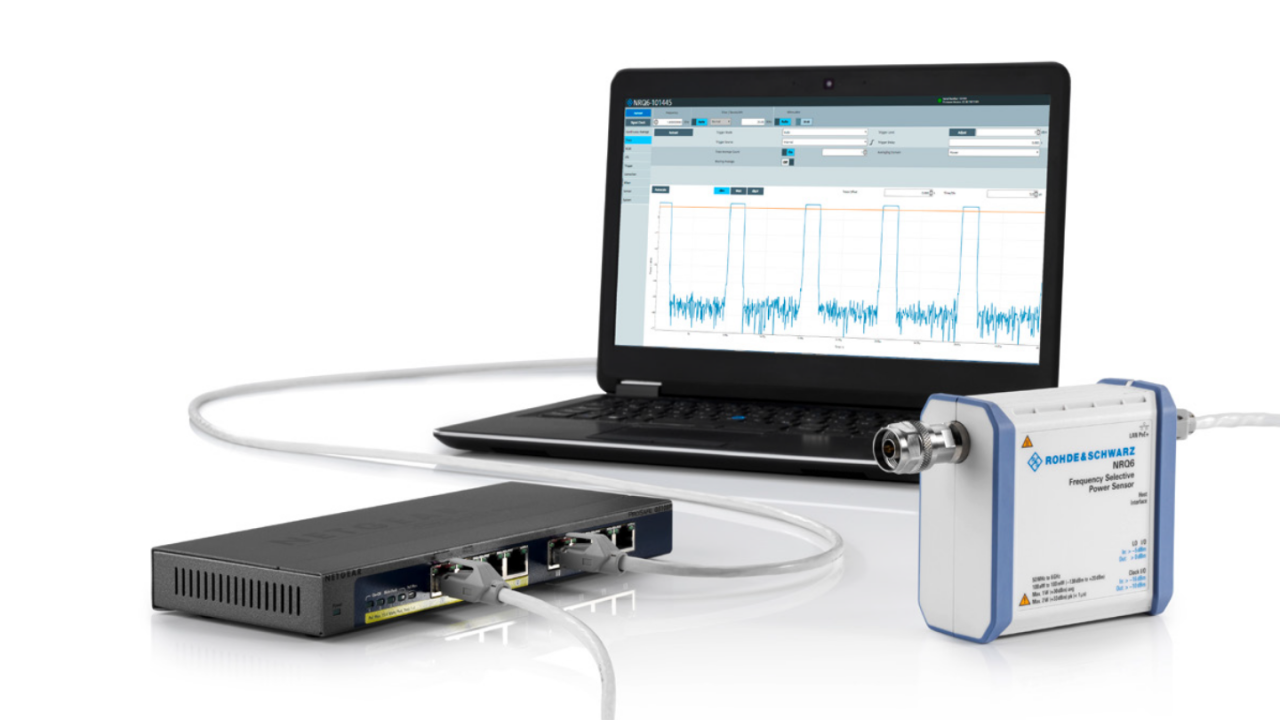
The R&S®NRQ6 is based on a receiver architecture. It can perform band-limited power measurements on a selected transmission channel. It operates in the frequency range between 50 MHz and 6 GHz, down to –130 dBm. In this application, the R&S®NRQ6 captures a MIMO signal as a standalone RF frontend. It feeds the I/Q data to the R&S®VSE software for postprocessing.
R&S®VSE is the cloud-ready signal analysis software that brings the experience and power of Rohde & Schwarz signal analysis to the desktop. The R&S®VSE-K144 and R&S®VSE-K146 options are highly recommended for this application. The R&S®VSE-K144 option analyzes a 5G NR uplink and downlink signal for each layer, covering all carrier bandwidths from 5 MHz to 100 MHz and different modulation formats from QPSK to 256QAM.
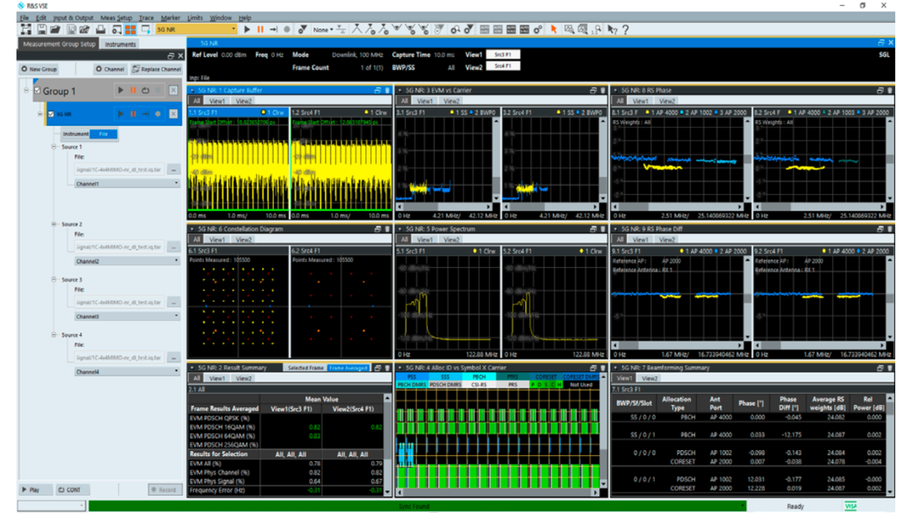
The R&S®VSE-K146 option demodulates the I/Q data and provides analysis results. It makes it possible to carry out 8x8 MIMO measurements for a 5G downlink signal. Demodulation of MIMO signals, measurement of the phase difference between antennas and beamforming characterization are additional advantages of this setup. It also supports many other 5G measurements:
- EVM
- Constellation diagram
- I/Q offset
- Gain imbalance
- Quadrature error
- Center frequency error (symbol clock error)
- Allocation summary list
- Channel decoder results
- Averaging over multiple measurements
Measurement setup
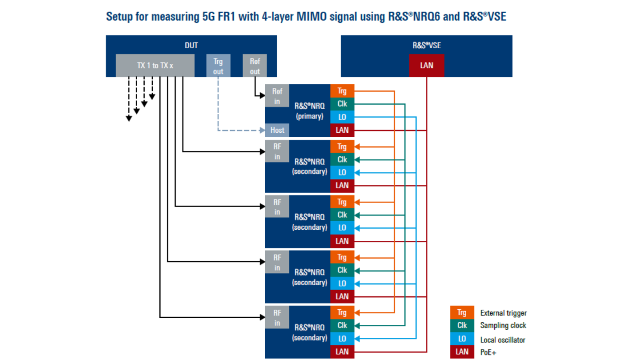
The measurement setup utilizes the principle of primary and secondary devices. The setup consists of one R&S®NRQ6 power sensor acting as primary device and four R&S®NRQ6 power sensors acting as secondary devices for capturing four MIMO phase coherent signals. All R&S®NRQ6 power sensors in this setup are controlled via LAN and require power over Ethernet (PoE+).
The primary R&S®NRQ6 provides three signals to all of its secondary devices:
- Trigger signal for synchronous acquisition
- Identical clock signals
- Coupling signal for the local oscillator (LO)
The number of secondary devices depends on the number of the MIMO layers. Each secondary device captures the data stream of one MIMO layer from the DUT. Subsequently, the RF signal is downconverted to the baseband signal and the I/Q data is made available to R&S®VSE for postprocessing.
Attention: All connections from the primary to each secondary device must be symmetrical. That means the cable lengths for external trigger, sampling clock and local oscillator (LO) must be identical.


Setup for measuring 5G FR1 with 4-layer MIMO signal using R&S®NRQ6 and R&S®VSE
Summary
This powerful setup can analyze up to eight MIMO layers simultaneously. R&S®VSE provides a LAN connection to all the R&S®NRQ6 power sensors while the R&S®NRQ6 makes the phase coherent I/Q data available to the R&S®VSE software for signal analysis. Data processing is performed by R&S®VSE, which also outputs data for the phase difference between the MIMO layers.


