Reverse battery voltage tests on electronic modules with automated testing capability

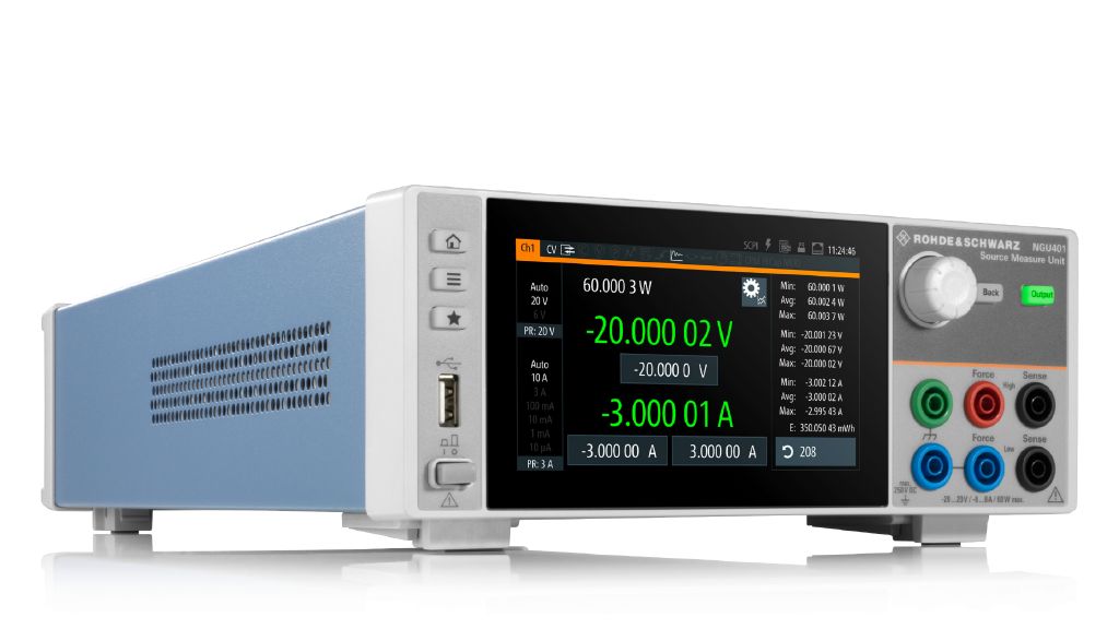
Electronic systems like electronic control units (ECU) must pass several stringent qualification tests in order to be approved for automotive use. These tests include a reverse polarity test which is specified as part of ISO 16750‑2. In line with the specification, the electronic module must withstand a negative supply voltage for a specific time without suffering any damage. The R&S®NGU401 source measurement unit (SMU) is ideal to perform this task, plus it provides automated testing capability.

R&S®NGU401
R&S®NGU401
Open Lightbox

Your task

Car batteries need to be repeatedly disconnected and reconnected, e.g. during service or repair. This involves the risk of connecting the battery with reversed polarity, which may lead to damage in the components and circuitry connected. Therefore, as part of the qualification test, every electronic circuit must pass a reverse voltage test. An electronic module like an ECU or a lighting control unit must be connected to a negative voltage for a time of at least 60 s. After the test, the module must not show any damage due to the applied reverse voltage. The test requires a power supply that can operate in quadrants I and III to supply the electronic module with power and to apply a negative voltage and current. Furthermore, suitable pass/fail criteria are needed to validate the electronic module.

A good approach is to accurately measure the supply voltage and current to determine if the electronic circuit is still undamaged after the negative voltage has been removed. Measuring the voltage and current with high precision before, during and after the test is a very simple way to detect a malfunction of, or damage to, an electronic circuit. Complex functional testing of the electronic module is not necessary. Furthermore, the application should be capable of automated testing especially when used in production environments.

Reverse voltage waveform in line with ISO 16750-2
Open Lightbox

Rohde & Schwarz solution

The R&S®NGU401 source measure unit is ideal to perform standard compliant reverse voltage tests since it can operate in quadrants I and III. It can power the electronic module during normal operation, apply a negative voltage and current for at least 60 s, and return to normal operation when positive voltage is back. The test sequence can be defined e.g. by using the internal arbitrary generator, or programmed externally and applied via remote control.

The measured voltages and currents can be used to support simple pass/fail criteria in an external test script. The R&S®NGU401 also provides a fast logging function with up to 500 ksample/s for voltage and current acquisition. The high sampling rate enables further, in-depth analysis. The voltage and current can be plotted over time in great detail using external tools. The instrument features full remote control capability, enabling automated testing.

Reverse voltage test setup with protection circuit based on N-channel MOSFET and diode controller
Open Lightbox

Application

In principle, performing a reverse battery voltage test is very similar to testing semiconductor devices with respect to their reverse voltage characteristics.

Common implementations of reverse battery protection circuits

A protection circuit to perform a reverse battery voltage test can be implemented in various ways. Very often, either a simple diode is used, or a discrete solution with a P‑channel MOSFET, or a diode controller in combination with an N‑channel MOSFET.

Using a diode controller with an N‑channel MOSFET will produce the lowest reverse current. However, this solution requires the ability to measure current of less than a few nA in the reverse mode.

Case study

A reverse voltage test with voltage and current measurements was performed fully automatically based on a Python script. Automated testing capability makes the application suitable for use in production, in addition to supporting the development process. A reverse protection circuit evaluation board based on a diode controller was used in combination with a loaded buck converter to simulate an ECU with a protection circuit.

Measurement of reverse voltage and current

  • Connect the R&S®NGU401 to the DUT as shown in the reverse voltage test setup diagram on the left
  • Establish a remote connection, e.g. over LAN or USB
  • Set a suitable current value for the overcurrent protection to protect the DUT
  • Run the Python script

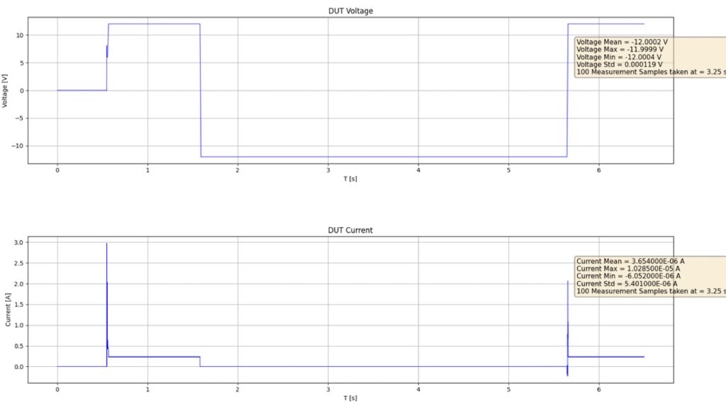
After the Python script has been executed, a window with the applied voltage waveform and the measured current will open. Results reveal that the current is approximatly 3.6 μA during the period the negative voltage is applied. This value corresponds to the allowed reverse current for the MOSFET according to data sheet specifications. Moreover, the operating current after removing the negative voltage is close to the value measured before the negative voltage was applied. The DUT has passed the test.

Summary

The R&S®NGU401 source measure unit (SMU) is an ideal choice for verifying requirements like reverse battery voltage protection for automotive applications. The R&S®NGU401 features four-quadrant operation, highly accurate voltage and current measurements and fast logging capability, enabling users to test their products with minimum effort. The R&S®NGU401 also provides remote control capability, enabling automated testing.

Voltage and current waveforms in the time domain (Python script)
Open Lightbox

Additional files

Register now and download the Reverse battery protection Python script.