Decoding secondary surveillance radar

Secondary surveillance radar (SSR) bridges the gap between communications systems and classic radar systems. Despite the increasing capabilities of mobile communications, SSR remains a major component in airspace surveillance.

State-of-the-art methods such as Mode S reply enhance SSR with broadcast-like capabilities and enable airports in remote locations to surveil the airspace even if no radar is available. More advanced techniques such as automatic dependent surveillance broadcast (ADS-B) utilize the infrastructure provided by a Mode S reply transponder to provide even more information for ground control and other aircraft.

Your task

As a designer of a transponder system, you want to ensure correct frequency emissions that fulfill regulations but also ensure that the actual data transmission is correct. The operating frequency of Mode S is given as 1030 MHz for the interrogator and 1090 MHz for the transponder's replies. An oscilloscope is a suitable instrument to verify the data content, since it allows you to decode the transmitted message based on a calculated pulse envelope.

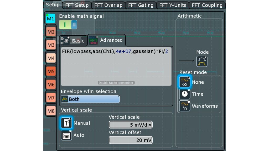
Fig. 1: Envelope of radar pulse via math channel
Open Lightbox

Rohde & Schwarz solution

The measurement conditions are simulated using the R&S®Pulse Sequencer software to generate Mode S data, which in turn is transferred to an R&S®SMW200A vector signal generator to simulate the SSR system. The R&S®RTP high-performance oscilloscope is used for analysis.

The Mode S message starts with a defined preamble followed by 56 or 112 pulsed signals (pulse position modulation) corresponding to 56 bit or 112 bit of data. The data format (DF) in use is indicated by the first five bits of data following the preamble. In this example, a DF17 (extended squitter) code is used, meaning the transponder is transmitting important flight information (e.g. a unique ICAO address or altitude) without interrogation periodically.

The analysis on the oscilloscope is as follows: a math channel is used to get the envelope of the radio transmission. This channel utilizes a lowpass filter of the absolute of the signal with a suitable cutoff frequency. A multiplication with π/2 ensures a correct amplitude (see Fig. 1). More information can be found in the application card “Analyzing RF radar pulses with an oscilloscope.”

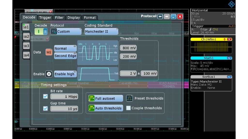
 Fig. 2: Manchester II decoding of the math (envelope) channel
Fig.2: Manchester II decoding of the math (envelope) channel
Open Lightbox

Further analysis is done via the R&S®RTP-K50 Manchester and NRZ serial triggering and decoding software option. The pulse position modulation is decoded by comparing the actual pulse change with a reference clock (here 1 Mbps). A “1” is decoded if the pulse changes from high amplitude to low amplitude (i.e. switched off) and vice versa.

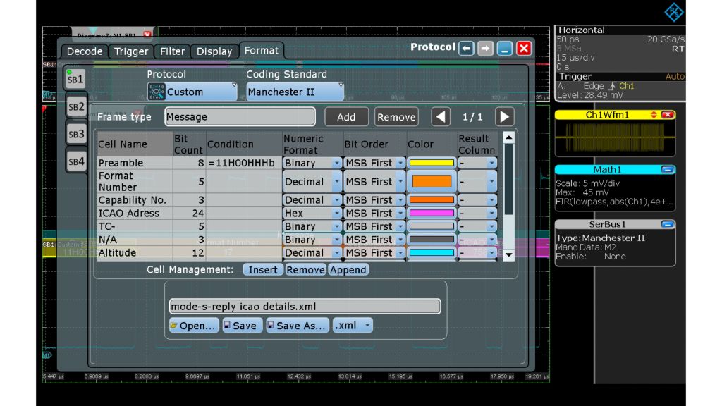
Fig.3: Format details of the extended squitter message
Open Lightbox

This corresponds to a Manchester II encoding. The setup of this custom decode is shown in Figs. 2 and 3. Knowing the format of the message allows several fields or cells to be identified in the message automatically.

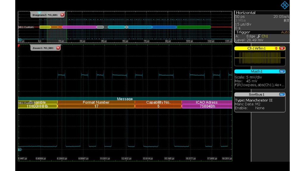
Fig. 4: Decode of a Mode S reply message (extended squitter)
Open Lightbox

Once the format information has been entered, the decoding of the Mode S transponder message is complete (see Fig. 4).

Summary

Pulse analysis of radars can take many forms and ranges from the analysis of the modulation to statistical analysis as well as well as data analysis of SSR. Mode S reply messages can be analyzed in an oscilloscope with one comprehensive tool. Modern oscilloscopes can easily handle the carrier frequency of 1090 MHz. Advanced math functions, which are included in the R&S®RTE, R&S®RTO2000 and R&S®RTP oscilloscopes, are needed to create envelopes of the transponder signal. The final function required for this application is the custom decode bus analysis on these signal envelopes.