Written by Magnus Hylén | September 4, 2017
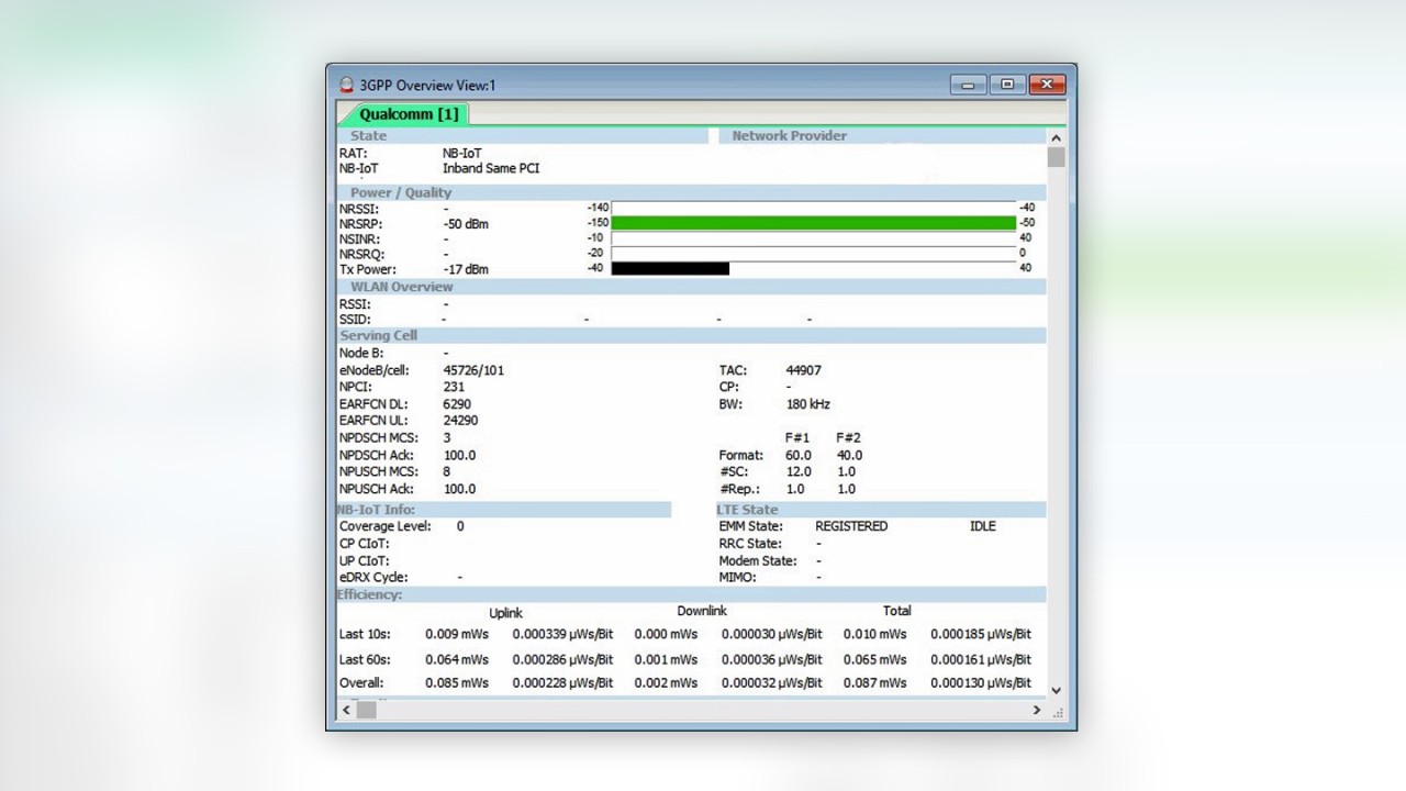
Once NB-IoT user equipment (Cat-NB1 UE) is attached to the network, it will provide the most important data about current RF conditions, including serving cell allocation and identity, downlink (DL) and uplink (UL) signal powers, and the actual configuration of NB-IoT specific features, such as Cellular IoT (CIoT) and coverage enhancement levels (CE).
How NB-IoT user equipment interworks with the network
A large number of NB-IoT modules and chipsets with different RF characteristics are already available on the market (and many more will follow). We should accept that they are designed to be less complex, less expensive, use less energy, and, consequently, cannot be compared to the feature sets found in smartphones.
To attach to an NB-IoT network, the Cat-NB1 UE must support the network’s frequencies – a somewhat tricky endeavor since the International Telecommunication Union officially divided the world into three Radio Regulatory Regions, in which each region has its own set of band allocation. However, the 3rd Generation Partnership Project (3GPP) has already specified many frequency bands for NB-IoT, mostly below 1 GHz.
The NB-IoT technology is optimized for small data transfers and minimal load over the radio interface. 3GPP standardized both IP and non-IP data delivery mechanisms, using either control plane or user plane signaling messages. During the attach procedure, the used connection type is controlled by the Cat-NB1 UE. The Access Point Name (APN) is the name of a setting belonging to the subscriber profile that is used to manage the characteristics of the connection between an operator’s network and an external network. For example, for IP and non-IP connections, different APNs are used.
Consequently, in this early phase of deployments, operators offer NB-IoT packages with a specific pre-defined NB-IoT subscriber profile that contains default APNs and data transport types that are implemented in dedicated SIM cards. This enables setting up the preferred connection between the UE and the NB-IoT operator’s network. Concerning the IP data, our field studies showed that the default APN connects typically to the public Internet, which is what we are used to when testing networks with commercially available smartphones.
What can be evaluated analyzing the behavior of NB-IoT user equipment?
After attaching the Cat-NB1 UE to the network, we executed initial tests to get an overview of the provided measurement data. Akin to legacy LTE measurements, we were able to detect the most important RF data, including serving cell information, RF power, and quality values.
After verifying these values, we set up a test script that could automate testing. R&S®ROMES4 provided the correct means in the form of its Data Quality Analyzer (DQA) module. Thus, we connected the DQA module to the NB-IoT UE using the modem port and set up our test script. The DQA script allowed us to switch the UE off, switch it back on a few seconds later and perform a series of ping tests. This enabled us to retrieve the data from a complete transmission cycle, including the “attach” and “detach” procedure.
Based on the transmit power, R&S®ROMES4 calculates the used energy of the UL and DL transmission. This helps users to estimate the “cost” – in terms of energy – that is necessary for the data transmission at specific locations. Power consumption is the key metric for the use of massive IoT applications where the targeted life expectancy of the devices’ batteries is 10 years.
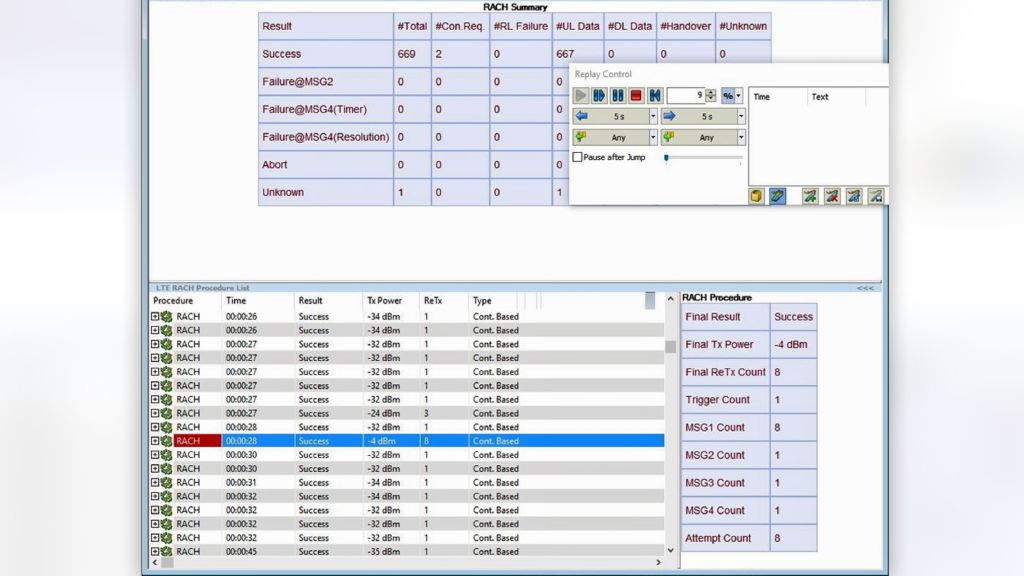
We were also able to obtain detailed information about the Random Access Channel (RACH) procedure that is used by the wireless terminal to initiate access to the network. The below screenshot shows an example of the RACH procedure with a high number of preamble retransmissions resulting in a high transmit power.
Another critical aspect of the NB-IoT technology is the extended coverage, which is required for various IoT applications such as smart meters that may be installed deep inside buildings. NB-IoT comes with several features that increase the effective coverage in challenging RF conditions, for example:
- Repetition of transmissions will increase the probability of receiving and decoding sent messages.
- The single-tone transmission mode is available for UL and subcarrier spacing of either 15 or 3.75 kHz. This mode boosts the power spectral density (PSD) by putting all transmit power in a decreased bandwidth.
- Using modulation and coding schemes (MCS) with low order modulation, such as QPSK, and lower coding rates, which offer additional protection of user-data bits, will result in a more robust transmission in situations where noise and interference become stronger than the wanted signal.
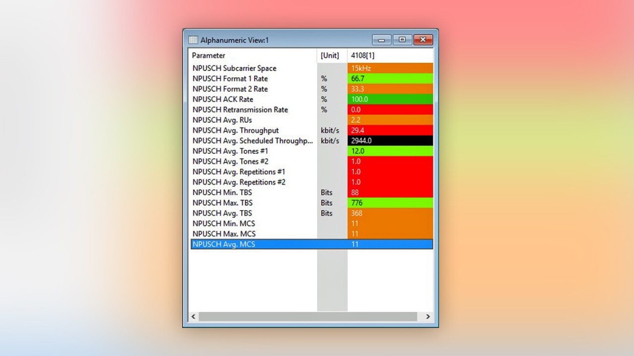
Using these features should not increase energy use; rather, the tradeoffs include reduced data speeds and increased latency. Below is an example of NPUSCH values in R&S®ROMES4 that visualizes all essential information about the UL transmissions.
What cannot be evaluated with NB-IoT user equipment?
Since the 3GPP Release 13, less complex and less expensive RF circuit designs can access the NB-IoT radio interface, limiting RF measurement capabilities as follows:
- NB-IoT is an FDD half-duplex mode access, the Cat-NB1 UE can only either receive or transmit, but never simultaneously
- Transmit diversity from eNB (TM2) is supported but not real MIMO (e.g., spatial multiplexing with TM3)
- NB-IoT UE supports cell reselection only in idle mode (e.g., neighbor cell measurements can only occur in idle mode)
In our findings, the half-duplex operation and the data transfer cycle of the test script limited the Cat-NB1 UE’s ability to perform continuous and accurate RF coverage measurements. Just like in legacy LTE networks, the output of measurement results can be irregular and behave differently between networks. This is because the UE idle mode measurement procedure is steered by the cell reselection parameters that are often set individually in each network.
Consequently, operators facing the NB-IoT RF coverage challenge are best equipped with a network scanner connected to state-of-the-art analysis software, for example, with the world’s first LTE/NB-IoT coverage measurement solution for drive and walk tests comprising the R&S®ROMES4 drive test software and an R&S®TSMx scanner.
Learn how to test quality of service (QoS) in NB-IoT networks in part 4 of this series.


