Quadrants des alimentations DC
Si un courant circule dans la borne de tension positive, l'alimentation agit comme une charge électronique. Il s'agit d'une charge de puissance au lieu d'une fourniture de puissance. Les instruments qui fonctionnent à la fois comme une source et une charge peuvent simuler des batteries ou des charges; ils sont appelés alimentations deux quadrants (ou quatre quadrants). proposent une architecture deux et quatre quadrants. Les instruments commutent automatiquement du mode source au mode charge. Lorsque la tension appliquée de manière externe excède la tension nominale réglée, le courant circule dans l'alimentation, qui est indiquée par une lecture de courant négative.
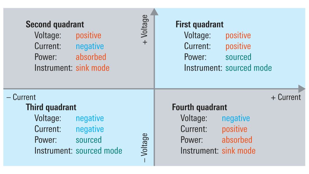
L'architecture des alimentations peut être entièrement définie en utilisant un système de coordonnées Cartésien. Les quatre quadrants illustrent toutes les combinaisons positives et négatives des tensions et courants. La figure ci-dessous illustre un système de coordonnées avec la tension sur l'axe vertical et le courant sur l'axe horizontal.
Comme mentionné précédemment, les alimentations standards génèrent généralement uniquement une tension de polarité positive (elles fonctionnent dans le premier quadrant), par exemple de 0 V à 20 V. Si une alimentation peut délivrer une tension positive ou négative sur ses bornes de sortie sans devoir commuter le câblage externe, elle correspond à une alimentation bipolaire et fonctionnera dans les quadrants 1 et 3, délivrant des tensions de –20 V à +20 V, par exemple. De tels instruments peuvent être utilisés, entre autres choses, pour tester le comportement caractéristique des semi-conducteurs pour des tensions bipolaires au point 0 V.
Les alimentations qui peuvent fonctionner dans les quadrants 1 et 3 proposent généralement aussi une fonctionnalité de charge pour les tensions et courants positifs et négatifs. Elles peuvent fonctionner dans les quatre quadrants et sont référencées comme des unités de source et de mesures (SMU). Dans le premier et le troisième quadrant, le courant sort de la borne de tension; l'instrument est en source de puissance. Dans le second et le quatrième quadrant, le courant entre dans la borne de tension; l'instrument est en récupération de puissance.


