Analog / Digital Design and Test

Dynamic re-referencing – microvolt-level measurements with the R&S®RTO oscilloscopes

In order to clearly visualize and make repeatable measurements on signals with amplitudes of less than 1/100 of a division, and stabilize signals captured over very long periods, the R&S®RTO oscilloscope’s powerful combination of measurement and math channel capabilities allows corrective offset adjustments on individual acquisitions more than one hundred times per second.

Your task

The task is to make precise and repeatable long-term measurements on small signals with DC offset or drift and lowfrequency noise components.

Examples

  • Small signal changes “riding on” large signals
  • Precise low-level measurements with minimum averaging and low trace-to-trace noise
  • Very-high-resolution, repeatable measurements at large vertical scale settings to accommodate signals with large dynamic range
  • Long-term measurements with consistent screen placement for easier visual analysis
  • Mask tests on very small signal amplitudes requiring reliable and consistent trace placement
  • Use of short averaging time for measurements with lowfrequency noise and drift/offset
  • Accurate RMS measurements on low-level signals
  • Signal changes that are referred to a changing baseline

Background

Modern oscilloscopes provide well-known tools to help reduce the effects of high-frequency noise, including analog bandwidth limiting, digital filtering, decimation and trace averaging.

Conversely, methods of dealing with low-frequency noise (thermal, flicker, 1/f) and drift are limited.

Offset is generally a fixed value for a particular sensor/ probe/oscilloscope channel, which may be simply adjusted or compensated for with a value that is used in a math channel equation (e.g. re-scale), by auto-zeroing or in an offset setting for a probe. In some cases, the offset value may be too small for the offset or auto-zero functions to fully cancel the offset voltage. In addition, the offset is subject to drift and usually affected by changes in gain or attenuation settings.

Drift is a phenomenon that is difficult to counteract; it is any change in the zero point or gain occurring over a period that is significantly longer than the sampling or measurement period. Drift may have both stochastic and deterministic components, caused by factors such as humidity, vibration, component aging, power supply variations (which are themselves subject to these factors), 1/f noise, radiation, changes in magnetic characteristics, and more.

Example

  • A sensor system has a positive, thermally induced zero point drift of 5 % of the measured signal amplitude over a 20-minute period, and 1/f noise that is significant below 1 Hz
  • If the acquisition period is one second, trace averaging of 60 gives one-minute averages; during that period, drift is 0.25 %
  • For every averaging period, 1/2 of the 0.25 % per minute drift will be eliminated. If the drift is continuous, averaging will only reduce the drift-induced offset by 0.125 % of the full-scale value, only 1/40th of the total drift-induced offset after 20 minutes
  • The 1/f noise is reduced, but may not be eliminated, as 1/f noise has no lower frequency limit

After this sensor system reaches thermal equilibrium, averaging will have no effect on the amount of offset in the zero point. Averaging can only correct drift or noise that occurs within a period that is shorter than the averaging period.

T & M solution: dynamic re-referencing with the R&S®RTO oscilloscope

In order to capture microvolt-level signals, the user can make use of R&S®RTO benefits, such as:

  • Low-noise frontend
  • HD mode, providing up to 16-bit resolution at 50 MHz, with simultaneous single-point control of bandwidth and resolution
  • Precise digital triggering on signals of as little as 0.02 division amplitude
  • Triggering on serial and parallel data buses to enable measurement and evaluation of “intelligent” system components
  • Excellent linearity due to frontend performance and single-core ADC with ENOB of > 7 bit at 1 GHz bandwidth
  • Powerful math channels with the following features:
    • Ability to use measurement results in math channel definitions
    • Trace averaging (in floating-point numerical format)
    • Flexible digital filtering with FIR and moving average
The principle of dynamic re-referencing
Open Lightbox

The principle

The Mean measurement, used with a gate, is performed on a part of the acquisition that is stable during every acquisition; the resulting value is subtracted from the trace.

The math channel waveform will then be locked to the reference level. This process effectively removes noise at frequencies below the acquisition period, including drift and offset.

If the selected reference is at 0 V, the math channel waveform will be re-referenced to “ground”. If the reference level is a known level that is not 0 V, then the measured reference level voltage is simply added to the math channel definition as a constant.

Setting up the R&S®RTO for re-referencing

Triggering

When the measured signal has level changes > 0.02 division, the R&S®RTO can provide a stable trigger.

If the signal has < 0.02 divisions of amplitude or drifts significantly, it is generally possible to find another trigger source that is synchronous with the signal of interest, such as:

  • A supply voltage change
  • A signal state change of an Enable or other control line
  • A command signal applied to the DUT via a serial bus, such as I2C, or one of the many other interfaces that can be used as trigger sources in the R&S®RTO

Reference measurement setup

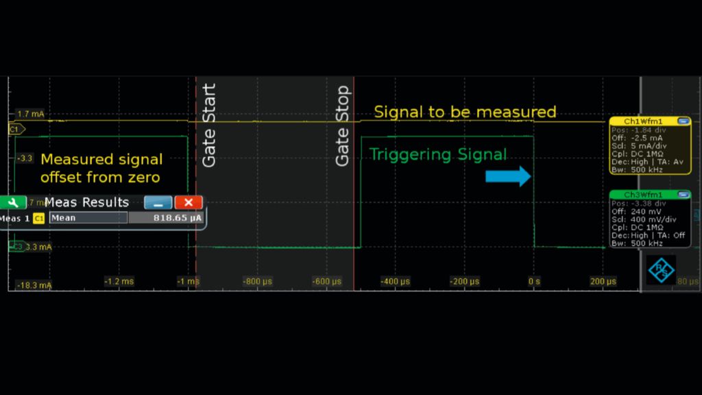
Typically, a Mean measurement is used to filter noise that may be present in the sampled signal, and a gate is applied to it to select a stable portion of the waveform as the reference.

The measurement setup requires first setting the source channel of the measurement, the type of measurement and finally the gate period. (Note: The source channel must be active and the State box checked to make the gate selection visible on the screen.)

The gating Start and Stop times are adjusted to match the desired reference part of the measured waveform. In the example shown below, the zero volt section of the trigger waveform (Ch3Wfm1, in green) corresponds to the zero current part of the measured waveform (Ch1Wfm1, in yellow). As a result, it is easy to see where the gate needs to be placed.

Sample signals and configuration.

Math channel setup

After the measurement has been defined, it is ready for use in a math channel formula. When the stable part of the signal is zero or is to be used as the baseline, the math channel formula (using channels and measurements as above) is as follows:

Ch1Wfm1 – Meas1

Math channel basic setup.

When the nonzero reference is a known value, e.g. measured to be 3.65 V, the formula would be:

Ch1Wfm1 – Meas1 + 3.65 V

Math channel formula entry.

In the math channel Setup tab, it is advisable to select Vertical scale > Manual.

The user may also select additional signal processing options with the Mode button/dropdown menu: envelope/average/RMS

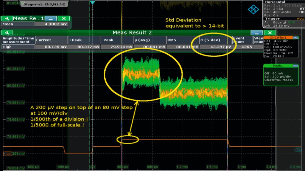
Measuring a signal of 1/500th division amplitude and 1/400th of the main signal.

An example

The following is a good example of re-referencing, with an effective math channel zoom factor of 500 and a measured signal level amplitude of 1/500th of a division.

The waveform to be measured is repetitive, a 256 Hz signal with a 200 μV level change that is superimposed on an 80 mV signal with two 40 mV steps (red trace at bottom). This shows the large dynamic range possible with the R&S®RTO, measuring a signal that is only 0.02 % of the 1 V full-scale value.

HD mode is used with a 20 kHz bandwidth. The math channel is set to 20× averaging.

On the oscilloscope screen (10 s persistence setting), the 200 μV signal is clearly visible, with an offset equivalent to 400 divisions. The persistence shows the stability of the signal, and the measurement statistics confirm the signal’s standard deviation of 44 μV (approx. 0.004 % of the fullscale value, > 14 bit).

Summary

Dynamic re-referencing enhances the use of the wide dynamic range provided in the R&S®RTO, allowing greater precision and ease of use and reducing long-term measurement errors.

Related solutions