Measuring antenna patterns of automotive radars
The antenna patterns of automotive radars provide a wealth of information that is of vital importance during radar development and validation.

The antenna patterns of automotive radars provide a wealth of information that is of vital importance during radar development and validation.
The antenna pattern is a key characteristic to be measured in automotive radars during development and validation. From the antenna pattern, many characteristics, including half power beam width (HPBW), peak-to-side lobe ratio (PSLR), antenna gain and sensitivity, can be derived.
To obtain accurate, conclusive and reliable measurements, the far-field condition has to be fulfilled. With an increasing number of automotive radars operating at 79 GHz and having an aperture size of 15 cm or more, this condition is hard to fulfill since a measurement distance of at least 12 m is required.
Another drawback is that measuring the full 3D antenna pattern at high resolution is extremely time consuming. Not only do the measurements take a long time, a considerable amount of time is also needed for the measurement setup and to make sure all components are properly aligned.
Rohde & Schwarz can offer the ideal system for this task. It comes in the form of a compact and movable anechoic chamber and is tailored to the needs of automotive radar testing. It consists of an R&S®ATS1500C antenna test chamber for automotive radar sensors, an R&S®AREG100A automotive radar echo generator and an R&S®NRP8S three-path diode power sensor. This simple setup delivers high-quality antenna pattern measurements that fulfill the far-field condition.
The R&S®ATS1500C antenna test chamber contains a premium CATR reflector that provides a large quiet zone, making setup simple and quick since minor positional variations of the DUT will not affect measurement results in a CATR. The chamber can accommodate automotive radars with up to 30 cm aperture size, and the antenna pattern can be measured using a high dynamic range power sensor through a calibrated path of the R&S®AREG100A.
Thanks to the 3D tilt-tilt positioner, the antenna polarization of the radar under test (RUT) is always kept aligned to the feed antenna polarization. This enables high-speed antenna pattern measurements without any compromise in quality.
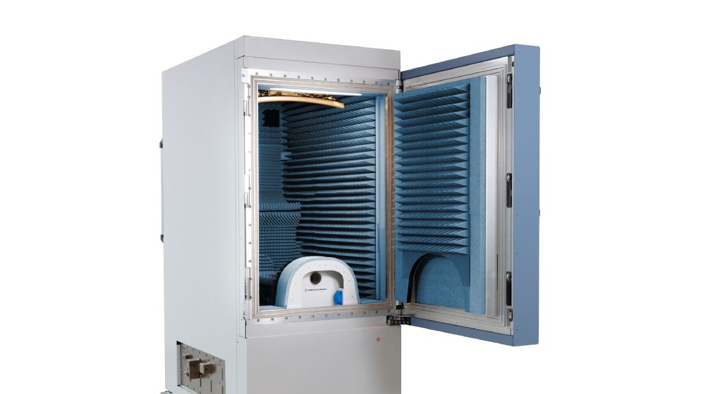
R&S®ATS1500C
R&S®ATS1500C antenna test chamber for automotive radar sensors
The R&S®ATS1500C has a unique vertical CATR design that not only offers an unrivaled quiet-zone-to-footprint ratio at 79 GHz, but also has a carefully designed layout with highquality absorbers to eliminate ghost targets caused by unwanted reflections.
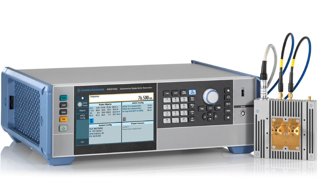
R&S®AREG100A
R&S®AREG100A automotive radar echo generator
The R&S®AREG100A is a smart and robust solution for radar target simulation in terms of distance, radar cross section (RCS) and speed. It features a calibrated path to which power sensors can be connected, as well as IF ports for signal analysis and interferer injection.
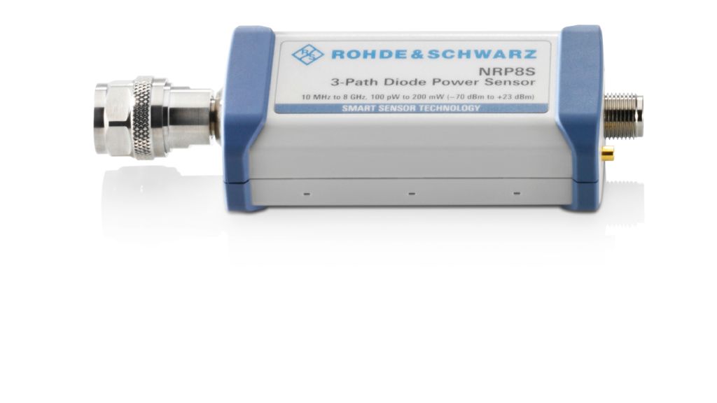
R&S®NRP8S
R&S®NRP8S three-path diode power sensor
The R&S®NRP8S power sensor uses three separate diode paths, each operated in the optimum detector range. As a result, the average power can be determined with high accuracy irrespective of the modulation type. The sensor provides up to 93 dB dynamic range with an excellent lower measurement limit of –70 dBm.
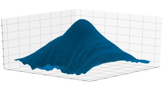
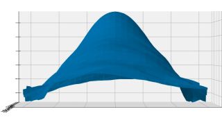
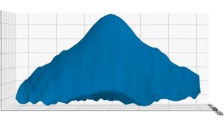
Measurement results
The antenna pattern is measured using the hardware setup shown above. Hence, setup time is short, and the farfield condition is fulfilled. In this example, a measurement range of ±60° in azimuth and ±30° in elevation, switchable in 1° steps, is used.
High-quality, CATR based OTA test chamber providing far-field conditions in a minimal footprint