Analisi dell'anello di controllo

Analisi dell'anello di controllo

Modulazione nel convertitore di potenza

La modulazione dell’ampiezza d’impulso (PWM), la modulazione della durata d’impulso (PDM) e la modulazione di frequenza sono uno dei cardini del principio di funzionamento di praticamente ogni alimentatore a commutazione o azionamento industriale. L’analisi e l’ottimizzazione della funzione di modulazione sottostante sono importanti per valutare il corretto funzionamento dell'anello di controllo di un circuito retroazionato. Gli oscilloscopi Rohde & Schwarz offrono funzioni dedicate di analisi che sono ideali per questa svolgere questa attività.

Your power supply control loop test challenge

Getting the happy medium stimulus signal level. If the injection level is too low, the gain will be too high, causing noisy results at low frequencies. On the other hand, some control loops are very sensitive to the injected level; a too-high level results in a too-low gain, causing nonlinearities or large signal effects.

In addition, the necessary stimulus signal level may change with frequency. Typically, a higher signal level is needed at low frequencies, and a lower signal level is needed at higher frequencies.

For control loop signals with a voltage measured in millivolts and a frequency in the kilohertz range, probes must have a suitable low noise floor to support high sensitivity and low signal-to-noise ratios.

Impedance in the loop forward direction must be much larger than in the backward direction in order not to change the behavior of the circuit

Our control loop analysis test solution

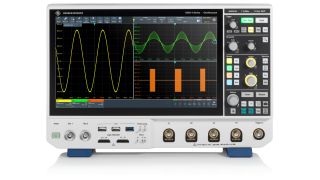
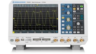
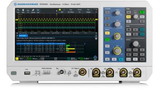
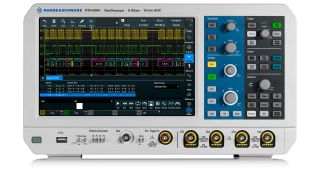
4 families of Rohde & Schwarz oscilloscopes all offer features, functions and performance that make them ideal for frequency response analysis for power electronics: the R&S®MXO4, the R&S®RTB2000, R&S®RTM3000, and R&S®RTA4000.

R&S®MXO4 includes market-leading 4.5 million acquisitions per second, resolution provided by the 12-bit analog-digital converter, and 0.00001 vertical division trigger sensitivity, based on the unique R&S digital trigger, now available in the mid class.

All three RTx oscilloscope families feature a 10.1" capacitive touchscreen with 1280 × 800 resolution, a 10-bit AD converter, 10 s boot time, 16 digital channels (optional) and a wide range of optional instruments such as logic, spectrum and protocol analyzers, arbitrary waveform and pattern generators, and a digital voltmeter.

The R&S®RTx-K36 option for any of these oscilloscopes provides Bode plot analysis; the oscilloscope’s internal signal generator provides the stimulus signal (10 Hz to 25 MHz). Low attenuation probes are available for all these oscilloscopes.

Products

R&S®MXO 4

Next generation oscilloscope for accelerated insight

More information

R&S®RTB2000

More information

R&S®RTM3000

More information

R&S®RTA4000

More information

Benefits of our analysis test solution

No need for an external signal source; the wave form generator built into the oscilloscope provides the stimulus signal (10 Hz to 25 MHz).

Running the analysis to investigate the stability is simple and straightforward, with a Bode plot function. The oscilloscope performs all the necessary parameter changes (with option K36). Simply turn the oscilloscope rotary knob to adjust the stimulus signal frequency, and observe directly on the oscilloscope screen how this affects the gain margin and phase margin.

A rigorous measurement procedure, especially since the optimum stimulus signal level may change with frequency. Use amplitude profiling to optimally match the signal level to the given frequency. Up to 16 steps in the signal level are supported.

Ideal probes for all supported oscilloscopes

Do you have further questions regarding our control loop analysis solutions? Please contact us.

Soluzioni di test per l'analisi della stabilità

Finding irregular effects in control loop design without compromise

The R&S®MXO 5 oscilloscope is a perfect choice for identifying irregular events in the control loop of power converters. Its digital trigger technology enables the user to define complex trigger events to isolate the root cause efficiently.

More information

Test dell’alimentazione del sistema di controllo del convertitore

I diagrammi di Bode sono uno strumento importante per verificare la stabilità del circuito di controllo degli alimentatori a commutazione. Oggi questa funzionalità è offerta anche dagli oscilloscopi. Questa nota applicativa spiega come si utilizza.

Maggiori informazioni

Suggerimenti e trucchi per i test di stabilità

Questa nota applicativa descrive come misurare la stabilità dell’anello di controllo degli alimentatori a commutazione. Spiega il principio di funzionamento e le applicazioni pratiche, guidando l'utilizzatore attraverso il processo. La misura è illustrata con una scheda di riferimento di Rohde e Schwarz di un convertitore di tipo buck progettata con Texas Instruments.

Scarica ora

Stabilità dell'anello del circuito di controllo

Questo webinar si occupa di misurare la stabilità dell’anello di controllo degli alimentatori a commutazione. Illustra il principio di funzionamento della misura, sottolineando le tematiche principali e descrivendo le misurazioni da un punto di vista pratico. Descrive anche le corrette configurazioni di misura e fornisce suggerimenti sui principali elementi di differenziazione tra le soluzioni disponibili.

Maggiori informazioni

Knowledge+

Experience the uniquely personalized, high-quality content from the whole Rohde & Schwarz ecosystem - all in a single place. Discover now our knowledge tailored for your needs.

Video center

Get access to interesting videos and webinars about solutions, applications and products.

More information

Download Center

Search the Rohde & Schwarz download center for brochures, datasheets, technical papers, manuals, firmware, software, drivers, and more.

More information

The Rohde & Schwarz Technology Academy

You’re in great hands
Practical knowledge. Industry insight. Real experts. Only with the Rohde & Schwarz Technology Academy.

More information

Argomenti correlati

Test dell’efficienza

Maggiori informazioni

Debugging e analisi EMI

Maggiori informazioni

Analisi della commutazione

Maggiori informazioni

Request information

Do you have questions or need additional information? Simply fill out this form and we will get right back to you.

Autorizzazione al marketing

La tua richiesta è stata ricevuta. Ti ricontatteremo a breve.
An error is occurred, please try it again later.